Last update, December 15, 2002
Building shown in this section is for reference in the Classic Build. Some links may no longer have a source and suppliers may not exist...Rick West, December 2009
The Rudder Servo Assembly
Choose the fastening parts for your individual mounting application
Parts:
Servo: A heavy duty with 100 to 135 torque units. Servo City
.064 aluminum strips, your stock.
.064 aluminum sheet, Online Metals or Tower Hobbies
.032 aluminum sheet, Online Metals or Tower Hobbies
4-40 SS Phillips machine screw, 3/8", Stock Item
4-40 SS Nylock nuts, Stock Item
#4 SS washers, Stock Item
Power switch, SPST, Radio Shack 275-634B
Tools:
Phillips screwdriver.
Pliers or nut driver.
Rudder Servo For RMG Winch Board

The Servo
The EC12 rudder will overpower the lighter duty servos during a run and in a blow. Without these servos the boat will power up into the wind even with good concentration on the helm. This rounding up is caused be the servo failing to hold the selected input. When the EC12 is completely overpowered downwind with a heavy servo running the rudder, it will broach and submarine to the hatch area. Then you know you have a good servo. If it spins out, you do not.
It is also recommended that the servo be water protected with Aeroplate at the beginning of each season or as part of diligence before a national event.
Mounting
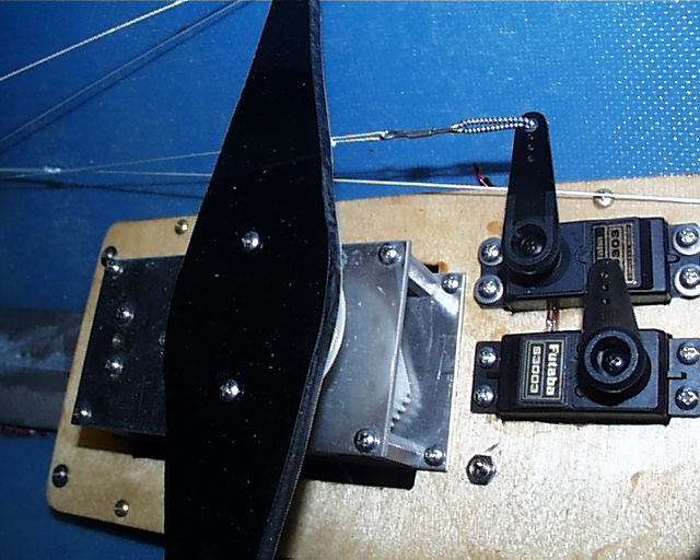
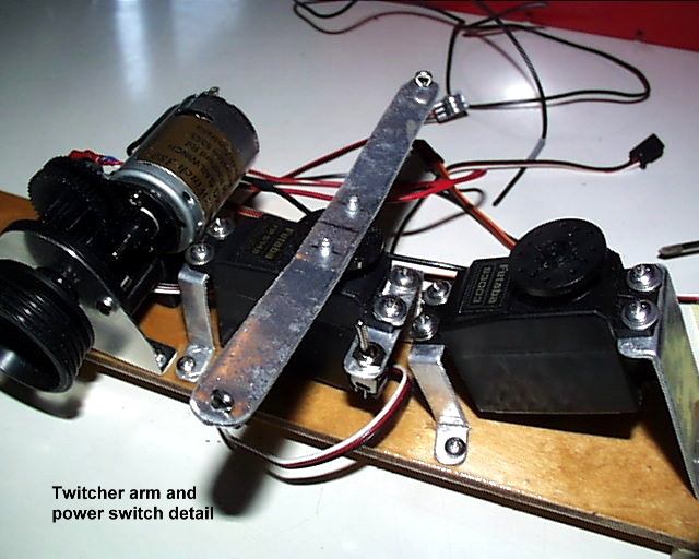
Make one mounting bracket from your stock of aluminum strips and drill the 3 holes needed for the 4-40 screws. This will be the "Z" shape. Note that the servo shaft for the arm is aft. Mount the bracket forward and on either side. Using the bracket, fashion a thinner piece of aluminum to sandwich into the forward bracket. Drill the holes to match the bracket and the size of the power switch. Install this on the servo, facing to port. If you do not want to mount the switch in this manner, it can secured to the bracket with a small nylon tie.
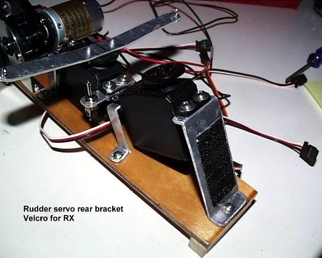
The above photos shows the wider rudder rear mount used to Velcro on the receiver. We now mount the TX under the hatch liner and then use a long Z mount in the place of the wider one.
Note: Retro to the photos here, the power switch is now on the rudder servo and the Velcro is not needed on the aft bracket.
The minor bend adjustments can be done later when it is mounted to the board.
The rudder servo assembly for a lead mounted system to the ballast is essentially the same as the board system. The aft bracket for the servo can be a "Z" shape or the wider one described above. Either will work fine here.
The base mounting holes are sized for a 6-32 cap machine screw.
Rudder Servo For The Swing Arm Winch Board