Last Update: March 08, 2012
EC12 Building Home Page
Special Presentation Home
Some Help in Building an EC-12 Boat or Rig
by Scott
Vernon (all photos by author unless noted)
 Want to
keep the cost of building your boat and rigs down? Save a lot of money plus get
the enjoyment of building your own rigs and gear and tinkering. You can buy an
EC-12 ready to sail, or in various stages of completion, but it is a boat that
you can build yourself once you have the class approved hull. You can do
everything from building a rudder to pouring lead for the keel to making sails
yourself. Many of us do. All of the many many parts can be fabricated or bought
from suppliers and of course many RC airplane parts are used. I will hold myself
back from talking about every single part that goes on an EC-12. There are
excellent sources of information available to you online and in books about
EC-12 building, setting up and racing. If there is a local EC-12 fleet then you
can go and meet the people and look at boats and see the things that you might
build. Regardless you might want to buy one or both Ragged Symmetry books which
have patterns for many of the specialty parts such as mast crane, stay and jib
racks and typical lengths for things like jumpers and spreaders. They are packed
with great and applicable info for you and I. Now there are parts like foam
glass decks and foam cored glass rudders available if we choose to spend some
money in order to make our job quicker and easier. The Manual has an extensive
list of suggested basic construction tools. If I were to recommend just one of
the books it would be Optimizing, but I am glad I bought both and refer to them
often. The books are available from the EC-12 class website, under the Class
Store button in the Clubhouse area.
Want to
keep the cost of building your boat and rigs down? Save a lot of money plus get
the enjoyment of building your own rigs and gear and tinkering. You can buy an
EC-12 ready to sail, or in various stages of completion, but it is a boat that
you can build yourself once you have the class approved hull. You can do
everything from building a rudder to pouring lead for the keel to making sails
yourself. Many of us do. All of the many many parts can be fabricated or bought
from suppliers and of course many RC airplane parts are used. I will hold myself
back from talking about every single part that goes on an EC-12. There are
excellent sources of information available to you online and in books about
EC-12 building, setting up and racing. If there is a local EC-12 fleet then you
can go and meet the people and look at boats and see the things that you might
build. Regardless you might want to buy one or both Ragged Symmetry books which
have patterns for many of the specialty parts such as mast crane, stay and jib
racks and typical lengths for things like jumpers and spreaders. They are packed
with great and applicable info for you and I. Now there are parts like foam
glass decks and foam cored glass rudders available if we choose to spend some
money in order to make our job quicker and easier. The Manual has an extensive
list of suggested basic construction tools. If I were to recommend just one of
the books it would be Optimizing, but I am glad I bought both and refer to them
often. The books are available from the EC-12 class website, under the Class
Store button in the Clubhouse area.
You can
make a rudder and pour your own lead ballast. Be very careful pouring lead;
especially to not overheat it, do not breath the fumes and do not let hot lead
contact water or moisture due to the danger of injury from exploding hot lead.
Pouring ballasts is interesting because you can read the words and see the
pictures in Optimizing and decide that you are going to pour the best ballast
shape ever. And you might just do it. Shaping and glassing a rudder is kind of
an art form and good therapy.
Suppliers
sell rigs for up to $300.00 or more. Do it yourself and you can buy a mast for
about $30.00, make booms from a second mast blank or use aluminum arrow shafts
for $5.00 or less each and add the odds and ends to make a rig (less sails) for
around $130 or less in your home shop. Minimal tools are required.
The EC-12
building site offers a great deal of help in building your own boat. Rick West,
our current class secretary, has created and maintained an amazing website that
is geared toward the home builder of EC-12s. It is
www.ec12.info . It is a very large site with page after page of great
information. It is fairly easy to navigate by subject/specific area being built.
The site assumes that the builder will buy a lot of the basic small parts like
spreaders and jumpers and stay racks from EC-12 specialty suppliers. I am going
to tell you here what to look for if you want to make those parts yourself. The
words and pictures on that site are still invaluable to you. Some listed
suppliers might be out of business, but current suppliers of similar parts to
those shown can be found on the EC-12 class website.
Let me tell
you some of what the Ragged Symmetry books contain:
The EC-12
Manual: (a lot of the following parts are shown with sizes or dimensioned
drawings in the pages following page 81) fixed mast top crane, brass tube
spreaders, jumper strut length, hounds and rigging of bowsies at the top of the
jib, stay racks, jib rack, mast step plate, locations of parts on the deck,
sliding hatch, rig tension meter, sailbox. Two well-built boats are shown in
detail, but many of the rig connections and adjustment parts are not per current
east coast racer practice.
Optimizing
the EC-12: Information on parts is brass spreaders, jumper struts, jib rack,
stay racks, mast step plate, locations of parts on the deck, ballast shapes, rig
tension meter, cradle pattern and building instructions, the useless weight of
paint, etc, etc.. One of the strengths of this book is telling you to worry
about making the best boat you can and how to do that. Also there is excellent
information on how to tune the boat. There is a lot of information that might be
considered over the top/too scientific, which is why some people have made the
mistake of putting these books in a box in the attic. I can email the lists I
have put together of great pages if you ask for it by email or on the discussion
group at the class website. The book talks about such things as weight and
waterline, hull trim angle (bow up or down), and optimizing the moment of
inertia through good boat building. Then after you launch, the boat it tells you
backstay tension, twist, mast bend and lateral mast bend, sail shape/fullness,
mast bend, jibstay sag, and sheeting angles for various wind and water
conditions. It talks about boom deflection and self-steering by the boat. Two
more well-built boats are shown in detail, and again many of the boom to sail
connections and rig adjustment parts are not per current east coast racer
practice.
Here is my
perception of the current state of EC-12 race boats on the east coast from a
complexity standpoint versus some of the information in the book Optimizing.
Moving the rig forward or aft from the standard 25.5 inch mast location is done
to balance the helm, but I do not believe the computerized CE (center of effort)
program has very many supporters among east coast racers. Moment of Inertia is
an important consideration and most people use what is considered a short high
ballast. That might be between 12 and 15 inches in length. Most people buy a
ballast and many cut an inch or more off the aft end and perhaps a little or a
lot off of the forward end depending on the ballast design. That allows the
builder to add (some of) that ballast back onto the boat to give the desired
hull trim angle (and also to ensure that the boat meets the waterline
measurement rule of between 42 and 43 inches) when the boat gets floated. Some
people still do pour their own ballast. One of the ballast shapes in the back
pages of Optimizing has a peaked top shape and that is a very good idea, either
peaked or curved top. Flat top ballasts also are big winners.
If you want
to build a boat or even a rig, start by looking at and/or running a copy of “the
construction guide” at
www.ec12.net . Click on “documentation” and then “EC12 plans”. The PDF is a
pop-up and it will take a bit of time to open. It has pretty much every
dimension you need to locate the parts and build a competitive boat. That
website is sometimes referred to as EC12web. It is mentioned in the construction
article in Model Yachting Issue 145, but with an incorrect address. There really
are a lot of information and good pictures on that site if you keep looking.
To start
building a boat contact a class authorized supplier of hulls and buy a hull by
going online to
www.ec12.org which is the EC-12 class website. You should become familiar
with a lot of the pages such as rules and the discussion group, but for building
you want to go to “Resources” “Class Suppliers” and see where you can buy major
parts such as hull, rudder, ballast, mast, another mast to use for making a
couple of booms, etc. There is a large amount of good build information in the
Discussion Group (under Clubhouse) on that site. It is a good idea to join in
and ask (and answer) questions when you are building and later when you are
racing. Read the class rules before and during construction. Understand them and
take care to build a legal boat.
You have to
buy a hull (from a class authorized supplier), and electronics, and it is
advisable to buy a mast and sails from an EC-12 specialty supplier, but
everything else can be bought from a specialty supplier, hobby shop, online
hobby supplier or home built. If you can afford it I would recommend buying a
ballast and rudder and perhaps a foam glass deck, but it is up to each person
based on his or her finances, abilities and ambition. Tom Germer tells in this
issue how to fabricate a beautiful and light wood deck, but I am sure there are
some people who feel it is enough of a challenge to install a supplier deck. For
construction of a structured balsa/glass deck the construction guide shows
patterns for deck beams and the build site shows procedure.
Here are
pictures and descriptions of building techniques for many of the systems and
parts that can be fabricated by the home builder. The design of the parts that
you build might be limited by your level of skill and/or your tools, but that is
why I am showing a few different ways to make a good gooseneck and a good vang.
Those are two major parts of an EC-12 rig and each of them can be simple or more
difficult to construct. It should be noted that these two mechanisms take a lot
of strain and some abuse in EC-12 sailing and racing. All parts of a racing
EC-12 need to be fabricated strong enough and maintained in such a way that they
do not fail in high winds and minor collisions. Some of the assemblies are not
very sophisticated and others look like they were made by skilled craftsmen.
When I say
glue, I mean epoxy or CA. Be sure to heed all warning labels and cautionary
information..
I will show
how to make goosenecks and vangs in the first part of this article, then rigging
the outhaul and other parts on the boom, jumpers and spreaders on the mast,
rigging the jib at the boom and the hounds, radio systems boards, words about
the rudder installation and long tiller fabrication.
Gooseneck using CB2212 butt hinges
This shows
the making a gooseneck using a set of CB2212 butt hinges available online from
www.mecoa.com. They seem to be a reliable supplier. This is past national
champion Danny Thomas’s boat and rig and this gooseneck is known to be reliable.
The CB2212 is plastic with a brass tube axis. Some people run one brass tube
full length thru both hinges instead of the two short axis tubes. I am not a fan
of the plastic clevises shown on the stays, but prefer brass Sullivan. It is
tricky to find the CB2212 on that website. Here is one convoluted path to
follow. Hit/left click on Tatone insignia bottom right on the home page. Hit
“Welcomc to www.Tatone…” Hit “Click here for control horns and hinges.” Hit the
yellow writing for the CB2213 hinge. Now you finally can see and order the
CB2212 hinge. Put it together and you might see that it will need a little
massaging to make it turn freely 180 degrees as it is made of plastic parts
molded in two piece molds. The way that Danny has built his gooseneck with the
barrel of the hinge right up against the mast does not put a lot of stress on
the hinge.

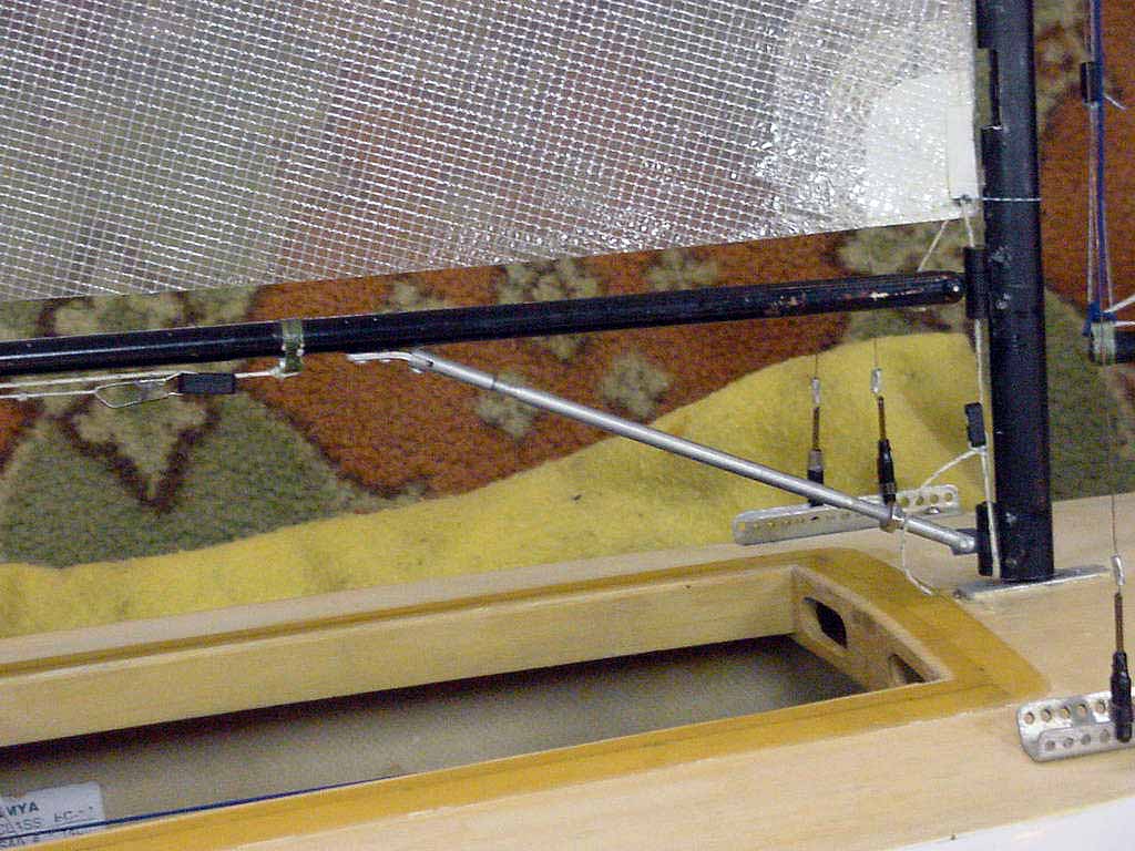
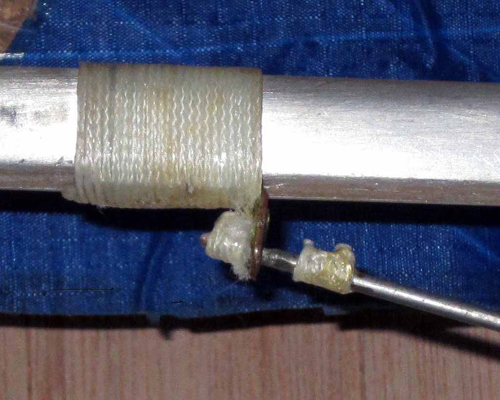
Simple and effective vang and detail
This seems
like an obvious design for a very simple and effective vang. This particular one
looks like the design got changed after the first few years of use. Maybe this
vang is not pretty enough for the pages of Model Yachting, but to me it
represents what someone who values function and simplicity can easily do and
redo on the kitchen table of their condo. The gooseneck parts are from a former
supplier, but the (top and) bottom part could be whatever you choose as long as
there is a RH threaded swivel ball link or Sullivan clevis on the forward end
for the rod to screw into. There is a brass L bracket wrapped (or screwed) to
the bottom of the boom. Chris Stater’s vang is 2-56 partially threaded rod, but
it could be 4-40 for added stiffness to support the boom. One thing about this
vang besides the fact that it is very simple to make is that it is pretty much
bulletproof if care is taken in the design and building. Another change that I
would make to it is to use short pieces of brass tube on the rod trapping the
bracket rather than the wraps of glued white line shown in the picture. I like
to put the little brass tube pieces as tight together against the bracket as
possible to eliminate play. The forward piece is just glued in place, as its
only job is to support the boom, and the aft piece is kept in place by (gluing
and) squeezing or pounding a wide flat on the end of the rod thus trapping the
not flattened piece of brass tube. It is vital to make it impossible for the
brass piece to ever slide off the end and vital to not rely only on glue alone
to withstand the high tension that an EC-12 vang is subjected to. One rule of
thumb with these boats is to not rely on epoxy or CA as a bond in any small area
on these boats that can be subject to high loading in tension. Pins and/or
screws are recommended as reinforcement, but not at the expense of drilling
though and weakening a small diameter part.
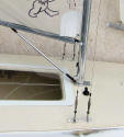
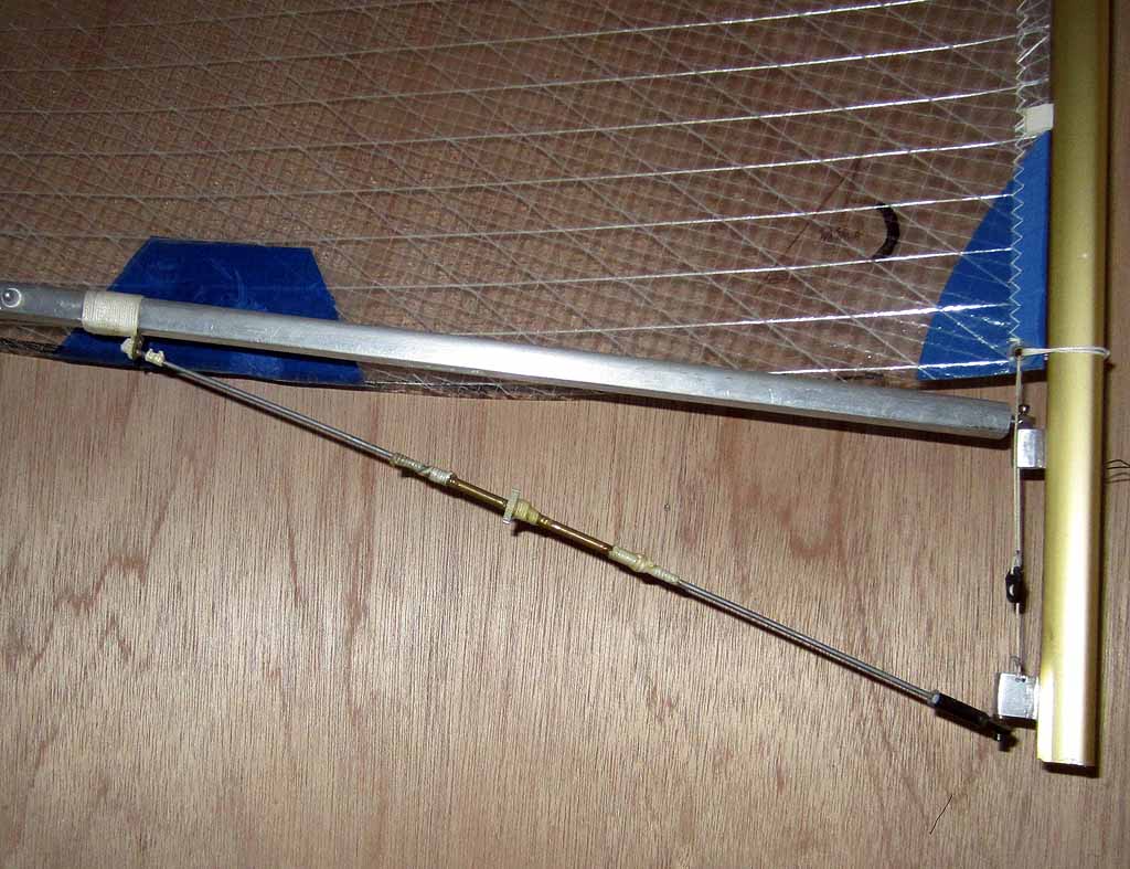
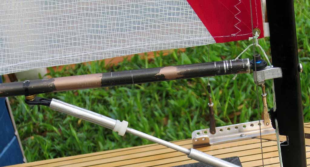
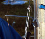
A more sophisticated gooseneck and vang
This is an
excellent gooseneck and vang. It is on Reichard Kahle’s boat. I saw this same
vang on Baron Bremer’s boat at the St. Augustine Nationals in 2009, but did not
get a presentable picture. I will describe the parts that I would use to make
it. Prepare the boom by cutting a slot in the bottom and a hole through the
sides for a pin or threaded screw so the ball link can be installed there.
Use a
couple of Dubro part number 2139 2-56 swivel ball links which take a 2-56 screw
but have a 4-40 size hole in the plastic barrel end. Take a Dubro part number
2157 steel turnbuckle and cut away the center un-threaded part. Take a 3/16 OD x
.049 wall Aluminum rod from a hobby shop or online supplier. Cut RH threads in
the forward end of the tube and in the forward ball link and LH threads in the
aft end of the tube and aft ball link.
Screw and
glue the RH thread end of the cut turnbuckle into the ball link, leaving the
good end of the turnbuckle (with unblemished threads) exposed. Do the same with
the LH thread part of the turnbuckle and the other ball link. Put a nylon stop
nut on the threaded rod at the gooseneck and assemble the vang as shown in the
photo.
Of course
qty 2 4-40 Dubro swivel ball links could be used instead of 2-56. And the Dubro
ball link could be screwed to the bottom of the boom as shown on John B’s vang.
The gooseneck parts are similar to what is shown in the next photo.
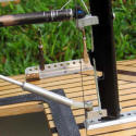
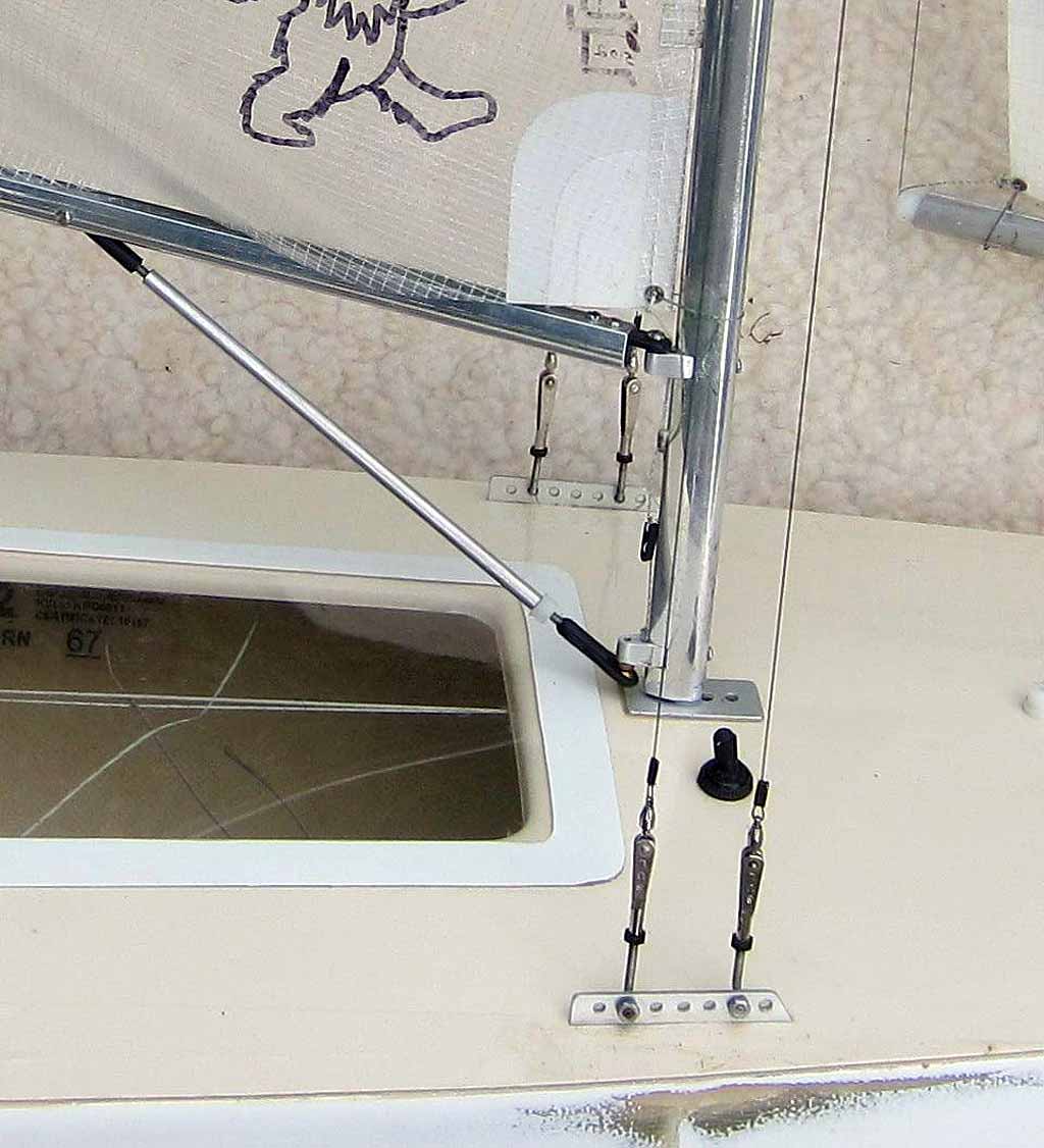
Gooseneck and Vee downhaul
This photo
shows a gooseneck similar to Reichard’s using a couple of small blocks of
aluminum shaped and tapped. It is a good strong way to make a gooseneck. In this
picture also take note of the Vee downhaul, which is the best configuration for
a main downhaul as it relaxes tension as the boom goes out due to geometry.
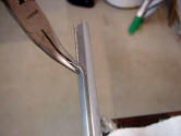
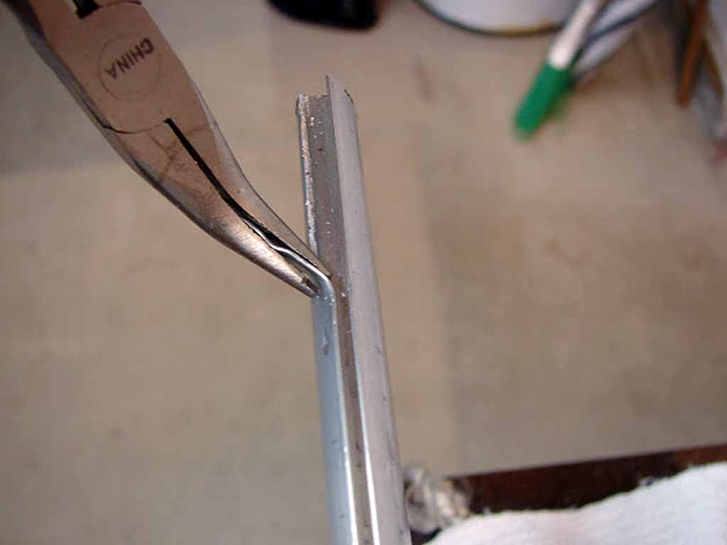
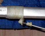
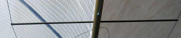
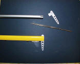
Removing mast luff groove using curved needle nose pliers
This shows
the process of removing the luff groove from a teardrop mast to make it into a
boom. At least two booms can be made from one mast. File the rough edge to be
smooth. This makes a good stiff light boom and is the most popular with the
class.
Lower lower stays
The short
stays clipped to the aft end of the stay racks are called lower lowers and are
generally only used in high wind. They were removed from his boat by Frank Vella
as soon as this picture was taken since the wind was light. They have fallen out
of fashion in the class due to the belief that they restrict fore and aft
bending of the lower mast. That bending de-powers the mainsail in high wind and
is a desirable thing. However, I am a fan of lower lowers. The benefit is that
sailing downwind in high wind they stabilize the mast’s sideways bend and keep
the boom end from rising which would add twist to the mainsail. Less mainsail
twist is desirable downwind in high wind as it makes it much easier to keep the
boat under control. This shows a very good way to attach them to the mast; a
loop which slips over the existing gooseneck screw. One way to allow the mast to
bend fore and aft, but not let it bend sideways is to rig the lower lowers so
they pull directly to the side. Perhaps the stay racks would need to be swapped
side to side. But the aft pull of the lower lowers is not necessarily a bad
thing as it allows use of more backstay tension (creating more forestay tension)
without the lower mast bending too much such that the lower mainsail develops
diagonal creases.
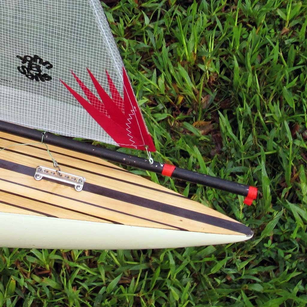
Boom and sheet attachment
Booms on
this boat are made from mast sections with the slot cut off. Notice the use of
ring dings attached to the boom for the sheet to clip to. A word of caution is
that those rings need to be at least one step up from the weak ones that we see
in the stationary department. The weak ones will straighten out and fail in high
wind. It is fairly easy to find the stronger ones, and I bought a big supply at
a fishing tackle store. The sheet loop is attached to the ring using a fishing
tackle clip. For the outhaul there is a small diameter aluminum or brass tube
glued into the hole at the end of the boom. The ends of the tube are rounded off
slightly to not chafe the outhaul.
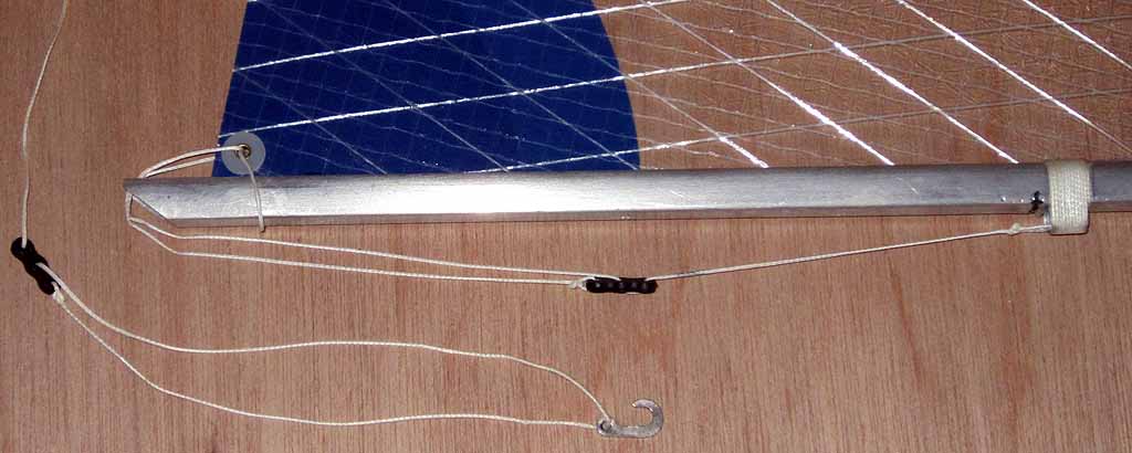
Outhaul setup
Chris
Stater’s main boom shows a way to rig up the outhaul. The angle cut is not
common.

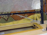
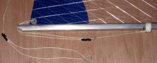
Homemade stay racks
Here is a
detail from an earlier photo showing stay racks, They are easy to make. John B
sometimes rigs up lower lower stays and has 2 holes for them to attach to. A
stay rack like this one can be made from whatever suitable piece of aluminum
extrusion you can find; maybe an aluminum front door sill which offers a lot of
possibilities due to its complex cross sectional shape. That sill will have a
tee which can be used to make a jib rack and a flat area for a mast step. John’s
jib rack is shown in another photo. The photo of Reichard’s vang shows his stay
racks which are homemade and are mounted through the deck. He puts a large
flange outboard of the upright part of the stay rack under the deck and files
the top surface so that it fits nicely under the fiberglass shear lip that is on
all of our hulls. No screws; just epoxy, I would imagine, and super strong.
Attachment of jib stay to boom and jib tee
This
picture shows one of the latest ways to attach the jib stay to the boom. John B
gets credit. The jib stay just disappears into a hole in the top of boom. Drill
a hole in the top of the boom and cut a thin slot aft of the hole with a Dremel.
Take a little metal ball from a key chain/light pull and drill out one end of it
oversized. Run the jib stay (out of the bottom of the jib) thru the ball
(entering the ball thru the small hole/with the big hole in the ball facing away
from the jib). Tie a knot in the jib stay wire - so the knot bottoms out inside
the ball against the small hole. Glue the knot inside the ball. Slip the ball
into the hole in the top of the boom. Pull it back into the slot and wrap a
piece of electrical tape over the hole (which is forward of the jib). Note the
hook at the jib tee. It is a good hook. I feel that the very popular 408 soft
metal hook should never be used on EC-12s. It straightens out and lets the rig
fall far too easily. The 408 hook can be identified with its reverse curve at
the end of the hook mouth.
All of the
stays on the mast can be rigged up similar this by drilling a tiny angled hole
in the mast for each stay, feeding an overlength stay wire though the hole up to
the top of the mast, putting a swage or ball on the end of the wire, pulling the
stay wire until the swage or ball bottoms out at the hole inside the mast and
then cutting the stay to length and adding the rigging pin and clevis at the
bottom of the stay.

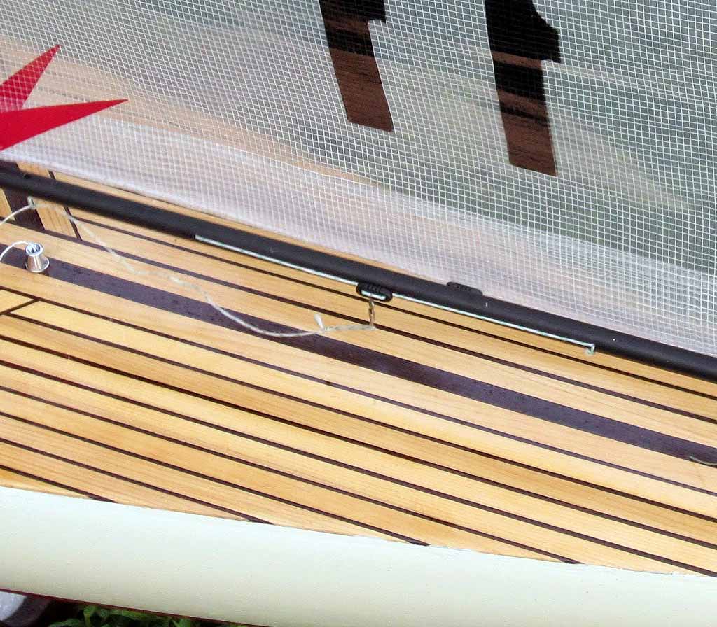
Sliding bowsie on the boom.
Shown here
is the bowsie that slides on a Dacron line along the boom. The Dacron line runs
through the front and rear hole of the bowsie and there is a separate small
diameter Spectra line running thru the middle hole of the bowsie from the boom
side. It goes around the Dacron line then back down through the middle hole back
toward the boom and a knot gets tied making that a tight loop. That loop makes
it so the bowsie will slide on the Dacron line but it takes a lot of pressure to
make it slide. Both the outhaul and the sheet length might get adjusted this
way. That bowsie setup is shown on the build site, Classic Rig, Main Boom
Assembly page.
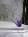
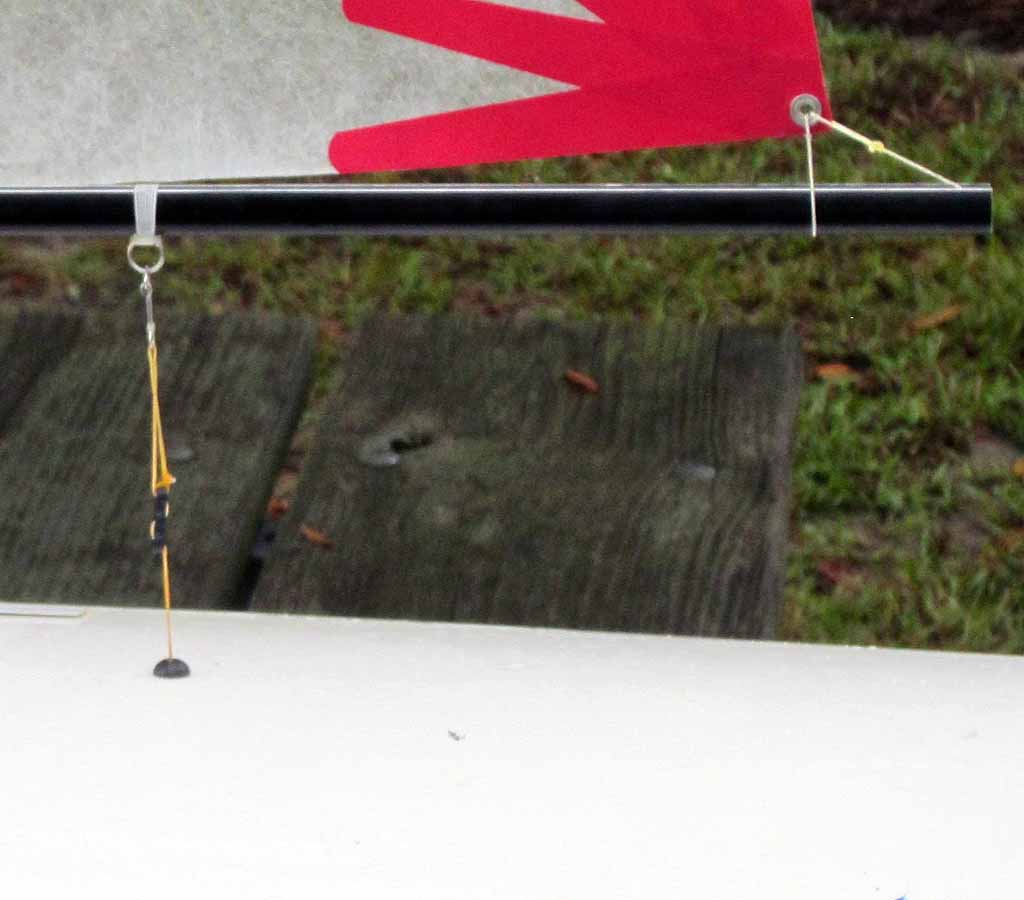
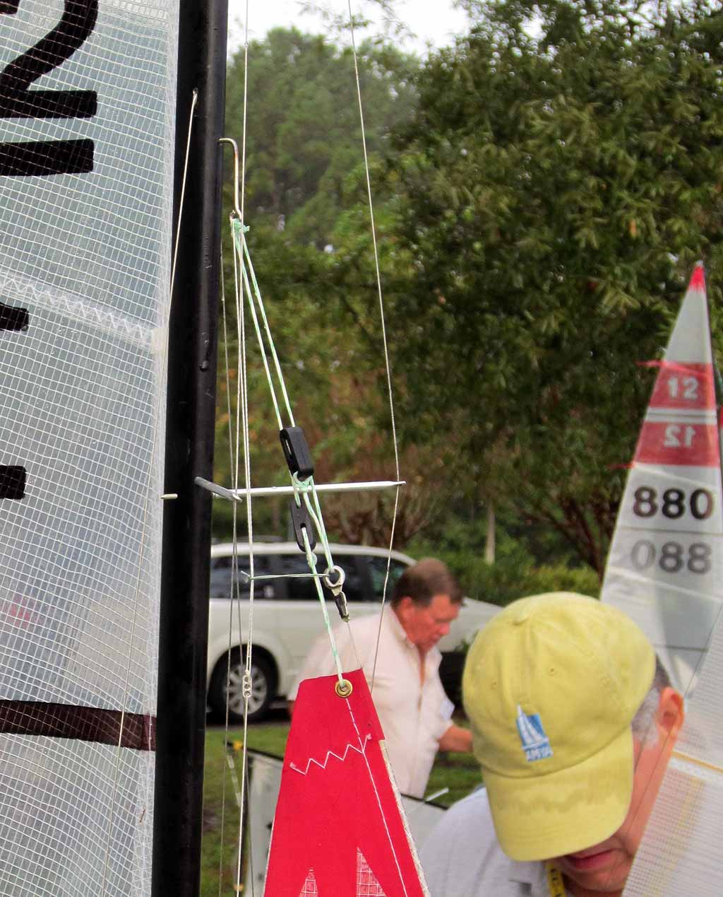
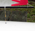
Jib topping lift
Shown here
is a topping lift which generally incorporates an elastic which is shown. The
topping lift maintains twist in the jib. It runs from the aft end of the jib
boom up to the hounds. Most topping lifts have a bowsie loop near the bottom to
control the amount of jib twist. The idea behind the elastic is that the aft jib
boom will lift in a strong puff causing the topping lift to go slack. On end of
the elastic is attached to the topping lift. The other end has a knot tied
around the topping lift allowing the elastic to slide and always have tension.
So when the topping lift goes slack the elastic takes up the slack and keeps the
topping lift from hanging up on the spreaders. I am not a fan of the elastic and
I use a 30# Spectra loop taped to each side of the jib luff and running around
the topping lift, taped at such a height that it prevents the topping lift from
hanging up on the spreaders and cut to a length allowing a proper jib twist
without the jib hitting the loop. It is important to have the loop end at each
side of the jib luff and not be threaded through the jib luff. I want the loop
to break loose in an entanglement not rip my jib. The loop is seen on
approximately one boat at any regatta that I enter.

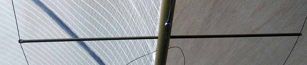
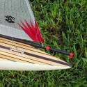
Homemade brass tubing jumpers
The jumpers
shown are misplaced as they should be about 3/8th inch below the hounds, but
they are good homemade jumpers. The mast is drilled to take the spreaders at a
50 degree angle and the continuation of each hole is a smaller hole that comes
out the side of the mast. The smaller hole is too small for the spreader to fit
thru, but is the size of the rod inside the jumper tube. The holes must be at
slightly different heights so that the jumpers can cross inside the mast. Jumper
length is generally about 2 inches. They can be brass or aluminum, but I would
recommend brass either 1/8 or 3/32 inch diameter. The outboard ends can be
pinched and drilled to take the jumper wires or a short piece of wire can be
bent double and inserted into the end of the jumper trapping the jumper wire.
Some people, like the owner of the fast and famous pink boat, do install the
jumpers about 6 inches below the hounds for some reason, so apparently location
is not critical.
Easily copied jumpers
Here is a
nice looking and simple set of jumpers from Sails ETC. It seems that it would
not be too difficult to make a pattern inspired by this photo and to fabricate a
set of similar jumpers.
Removable homemade spreaders
Removable
homemade spreaders are simple. These are 3/32 diameter brass tube with a 1/16
diameter steel rod inside. The ends are squeezed flat and drilled. The rod is
trapped in one spreader and runs through a hole in the mast that is just big
enough for the rod. It is important to make a nice clean small square to the
world hole in the mast. Some people, myself included, tend to favor 1/8 diameter
brass spreaders with a 3/32 diameter (or 4-40 in a pinch) steel rod inside, in
spite of the increased windage. They tend to survive entanglements on the water
better than the ones shown here. Neither of these spreader sizes breaks; the rod
just bends.
Masthead crane
This
picture is from Rick West’s build site and shows a good shape for a crane. The
mast gets slotted to accept the crane and the crane has a protrusion at the
bottom that fits down in the mast. The size and outline of a typical crane is
shown on page 61 of the EC-12 Manual. This photo shows a plastic hinge that will
be attached to the head of the mainsail. Do not use that. For some reason this
hinge became all the rage in the 1990’s, but it only was necessary for a
“rocking crane” that never did catch on. Current best practice is a grommet in
the head of the mainsail and Spectra loop tied through a small hole in the crane
along with the upside down Vee downhaul. For the groove in the mast, one file
that is thin enough to enlarge a cut made by a hacksaw blade (besides the flat
bladed needle file) is a metal nail file. Material can be aluminum about .063
thick if it is without lightening holes. The length of this crane aft of the
mast is 1 5/16 inch and thickness is about .08. I believe the crane shown is no
longer available to buy. By the way, be sure to cut the mast length to no more
than 71 7/8 inches if you have a 1/8 inch thick mast step. The rule says max
mast length including the crane is 72 inches measured from the deck.
The U of a
sliding cockpit hatch cover can be seen in various photos. There are detailed
instructions on how to build one on the build site.
www.ec12.info . At the time this is being written you need to go to the
“structured deck” page to find the link to the “install hardware” page which
shows info and pictures of the sliding hatch fabrication. There is no link
leading to it on the molded deck page. Rick promises to fix that soon, perhaps
before publication.
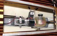
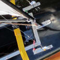
Radio systems board
Tom
Germer’s systems board/ballast/sheet line system as one unit is shown here. The
systems board with arrow shaft sticking forward is permanently screwed to the
ballast and at the end of the day he is able to easily remove it all for
inspection and ease of carrying the boat.
There are a
couple of websites that show good plans for a systems board.
http://www.ec12.info/Systems%20Board.htm Rick West’s site. Pick “the
chassis” button and also the “board mount” button. Pick the “sheetline system”
button and that will show you the current construction method which is to put
the forward bow block on an “arrow shaft” that is attached to the systems board.
You can see
that there is an arrow shaft running forward from the radio board on Tom
Germer’s boat. There are a series of good pictures of this on Al Stall’s build
page
http://tinyurl.com/7jnftcn One thing to take note of on Al’s page is the bow
block shaft retainer. Al used an arrow shaft running forward and it is necessary
to kind of jam that in up forward to keep it from wanting to bend under sheeting
loads. On the forward end of the shaft is a double block with the sheet loop and
tensioning elastic running through it. This detail has become normal practice
after an absence of a decade or more. What was old is new again. The benefit
versus a block attached to the hull or bulkhead up forward is much improved
access when the sheet loop breaks. The sheet line and elastic can be removed
along with the radio board as one assembly for maintenance. The overall beauty
of Al Stall’s build page is that you can see all of the parts that make up and
EC-12 and somewhat how they all go together on one single web page of thumbnail
images that can be clicked on and enlarged. Al shows the pattern for his systems
board on his page.
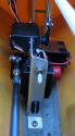
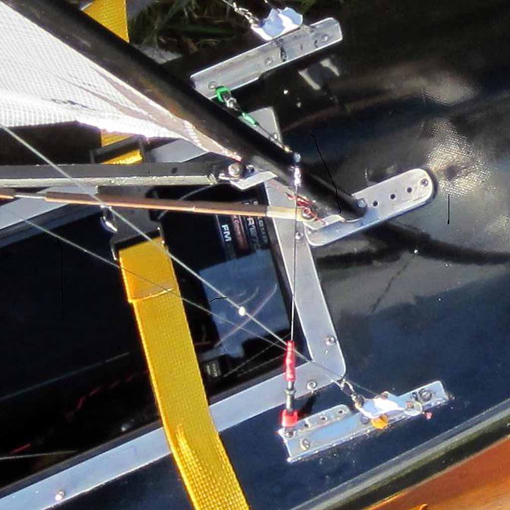
Vertical radio systems board
This
picture is of Dave Brawner’s vertical systems board. I will talk about rudders
here because the shaft length might determine what sort of systems board you put
in the boat. Most people seem to put a short rudder tube in their boat: one that
ends below the waterline. They put grease seals in the rudder tube and grease on
the rudder shaft to keep water out of the boat. The process is shown in the book
Optimizing and also on the build site
www.ec12.info. Hit “Rudder” in the hull section of the site. So those people
install a systems board like Tom Germer’s or, Rick West, or Al Stall. Dave
Brawner has a long shaft/long rudder tube which ends above the waterline in his
boat. If the rudder servo is installed with the servo arm off to the side then
it will be necessary to put a bend in the push pull long tiller arm or have the
pull lines at a steep angle or to raise the rudder servo in the hull. Dave
Brawner has done the more logical thing, which is to create a vertical systems
board with the (winch and) servos attached to the sides. The arms of both the
jib trim and rudder servos stick up in the air. This gives better geometry for
the jib trim servo as it gets the turning block up high near the sheet line, and
certainly better geometry for the rudder servo arm setup which allows the long
tiller to be pretty much horizontal. You will have to make a paper pattern of
what you think Dave’s system board looks like if you want to try to copy it.
Since this is such a less than useful picture I was going to leave it out until
I realized the benefit of a vertical systems board. The aft flange has a switch
and also the connector where the battery pack plugs in. The rudder servo can be
seen mounted on the left side of the board with its servo arm up high. The round
cap and black block on the right is an RMG280 type winch mounted on the right
side of the board. Above the winch is a jib trim servo mounted on the right side
of the board with its arm/axis aft. The board is bolted to the mast support and
perhaps there is a flange at the bottom so it is also screwed to the ballast up
forward. Screwdriver axis must be given some thought when laying it all out
beforehand. Dave’s 1990’s era boat does not have a sheeting loop arrow shaft
running up toward the bow, but a modern build would probably include that.
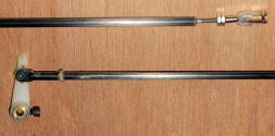
Push-pull rudder system tiller tubes
This
picture shows the long tiller for a push-pull rudder system. Dubro 2-56 or 4-40
partially threaded rods are used plus lock nuts. These are carbon fiber tube or
arrow shaft. Many people use a pull-pull system.
A backstay
eyebolt is needed but not shown. One possible choice is the Sullivan S549
threaded 4-40 eyebolt. With this eyebolt it is recommended to use a washer both
above and below deck to keep it from wanting to enlarge the hole and wobble and
rotate. I think a dab of glue in the deck hole would be good as well. It is best
to orient it with the hole fore and aft and hook it from aft to prevent snagging
lines on other boats. Most people use a model boat parts supplier piece.
I have not
written about rigging up the sheetline system. It is not easy to take pictures
of that on a completed boat. It is best to look at it on Rick West’s build site
by clicking on the “sheetline” button. On your boat it is a good idea between
regattas to sheet all the way out and also to relax the elastic. I like to clip
a “remove before flight” clothespin with a blue masking tape flag on my deck at
the hatch opening to remind me to tighten the elastic before launching. A loose
elastic can lead to the sheets coming off the drum when sheeting all the way
out.
I hope this
helps a bit for anyone thinking of or trying to build an EC-12. I believe the
question of why I never got a job as a technical writer has been answered.