Last Update: April 12, 2012
EC12 Building Home Page
Special Presentation Home
EC12 Class
Special Presentation for the American Model Yachting Association
Model Yachting Magazine Summer 2012 Issue #168
Site prepared by Rick West, EC12 Class Secretary
This presentation supports the magazine EC12 Class Feature Articles.
(Most images are minimized; double click to enlarge)
Articles Presented from originals:
Modular Building Approach, Rick
West, San Francisco
Short Kit
The Hull
The Rudder
Removable Ballast
Deck Mast Step
System Board
Custom Decking, Tom Germer, Jacksonville FL
Tips in Building, Scott Vernon, Atlanta area
Lithium Batteries, Richard Hedderick, Naples FL
Radio and Batteries, Rick West, San Francisco
Modular Building Approach
The traditional method of building a sailing model has been through brick
and mortar phases of construction. Driven by racing considerations,
those phases have moved to modular building then assembling the model. This
concept also considers a interrelationship of key modules to each other then
assemble the model in an order convenient to the builder. The heart of this
is the treatment of the radio gear, sheetlines, the deck and the ballast in
the model. These modules share consideration with each other mechanically
and physically toward sailing properties and performance. Added to this is
the ease of building, convenient maintenance and better physical handling of
the model out of the water.
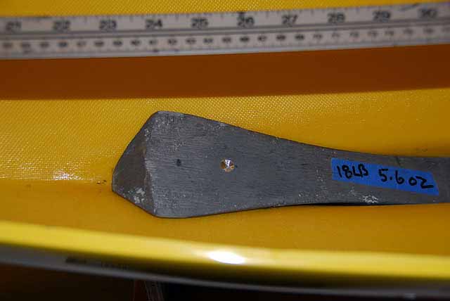
Since the standardization of the EC12 hull development of a one design mold, ballast from casts will fit all the hulls regardless of the manufacturer. The cast for the ballast is not standard with respect to weight and size. There are many ideas on this. A piece can very in length by a couple of inches and some venders offer weight selections. The most popular is 18.5 pounds and between 13 and 14 inches long. This is not to be confusing but to point out that we are hobbyists and enjoy our own craftsmanship. Performance differences is questionable and good lakeside chat.
The System Board is a building concept to consolidate the sheetlines and the radio gear into one removable unit. It is not tied to specifications. It too is personalized by the modeler. However, ballasting and using the SB concept are tied together by any sailboat modeler to have low righting moments and proper balance to the lines of the boat. Moreover, sail plan forces dictate the mast step position on the deck and through its support to the position of the ballast and the SB.
The last factor in this preparation to build is how the ballast will be installed. The latest consideration in the class, and within months of this writing for Model Yachting, is removable ballast for the EC12 model. The thought that the ballast does not have to be sealed into the keel has brought to mind long standing issues we have born. There is no need or reason for the ballast in the model except while in the water.
|
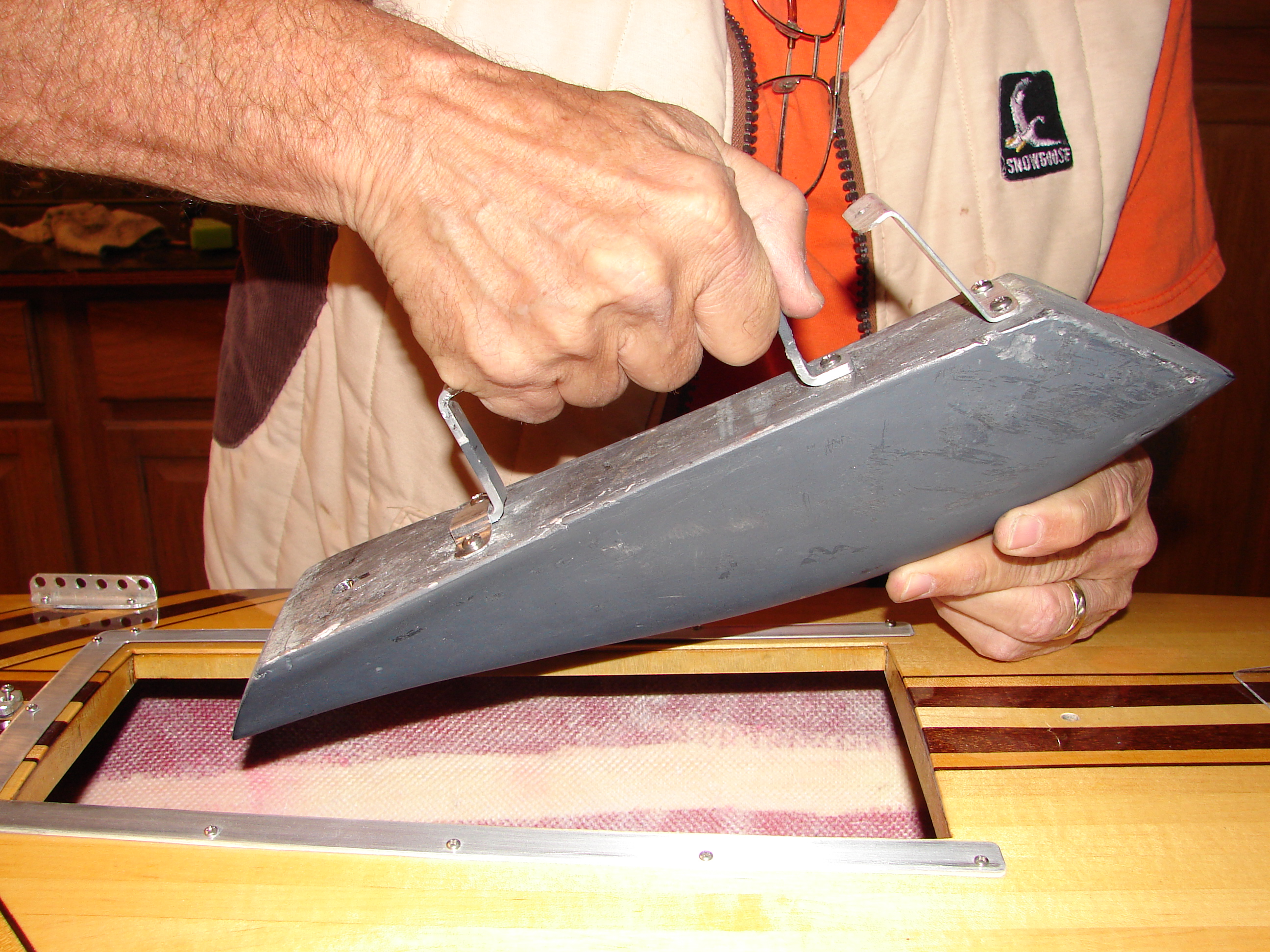
There is no need to carry a 23 pound boat with two hands in front of the navel. | |
|
The boat can be handled anywhere with one hand by the hatch opening without reinforcement. | |
|
Storage and transport options for the model is simplified and more convenient. | |
|
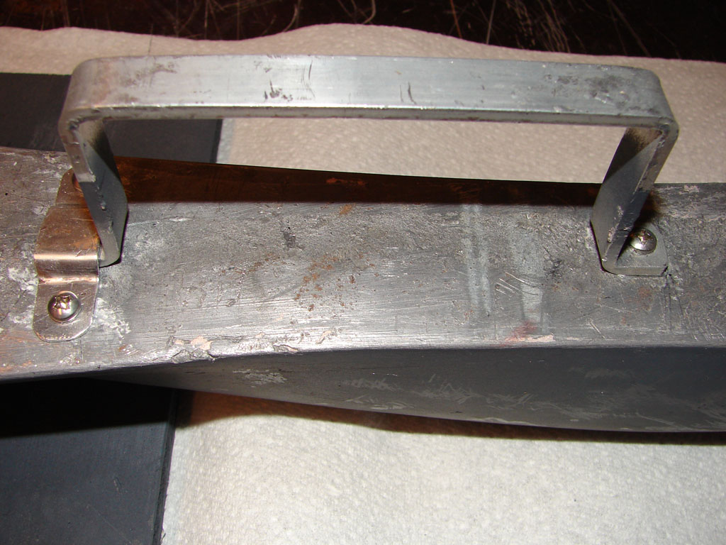
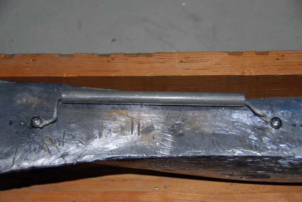
Ballast can be carried by your side with on hand by a handle. | |
|
Gravity and thermal pressures on the keel are all but removed from the spreading of the keel width. This is currently a class rules problem. | |
|
Airline travel as sports equipment becomes less expensive with easier handling. The ballast can be carried in personal luggage with some sacrifice. | |
|
As we grow older, more benefits will surface. |
The presentation of these changes in building the EC12 are from innovations showing up at the lake. This is one thought of many and in just one shop. There are a lot of ideas but the concept and goals remain the same.
Short Kit
The class approved manufacturers provide the hull, deck, rudder and ballast as a package. Most provide the deck with the hatch cutout finished. Each are handled separately here and prepared to completion.
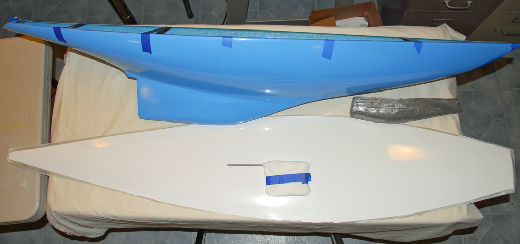
The Hull
This can be done in two short shop sessions.
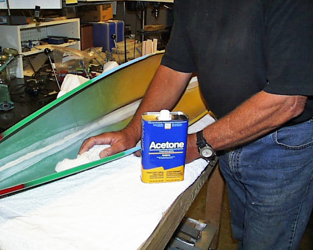
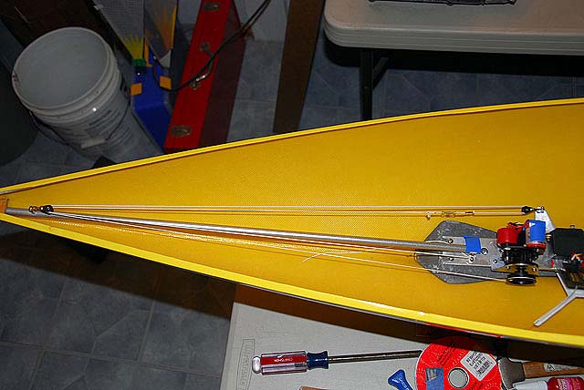
The hull is clean inside and out and fair with 1600 grit wet paper. The flange where the deck will be mounted is sanded and cleaned. An ounce of resin is poured into the bow to strengthen the fabrication against collisions and other navigation mistakes. A piece of resin sealed wood is glued into the bow horizontal to the water line to act as a wedge that will retain the bow end of the System Board winch line boom. The ballast is placed in the keel. It only fits in one place but we like to fuss with it. The casting will be marked on the hull for its position fore and aft. The top of the ballast will be marked where the mast will be directly above. Station 25.5 works good for the EC12. Drill a dimple in the casting on the mark. This will hold the removable compression strut for the rig. The ballast is removed and a small chock is glued to the keel at the aft mark. This will keep the ballast from moving aft from vibration in the water. It will not move forward because of the compression strut. (More on ballast below to consider.)

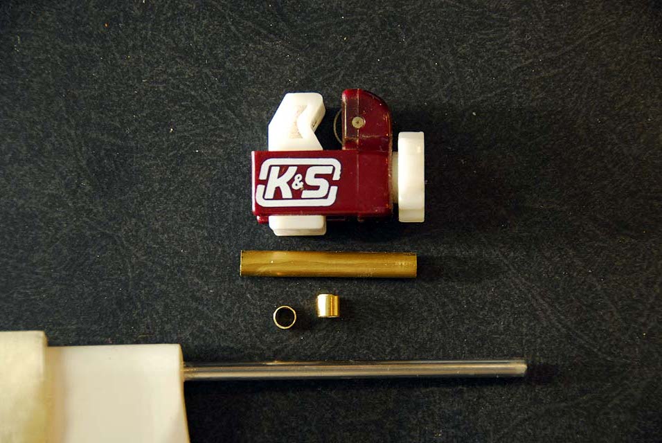
The Rudder
Session one:
Make two grease seals from tubing that will fit over the rudder shaft. Secure them to the lower part of the shaft with CA. Size a tube that will sleeve over this that will extend into the hull to the tiller.
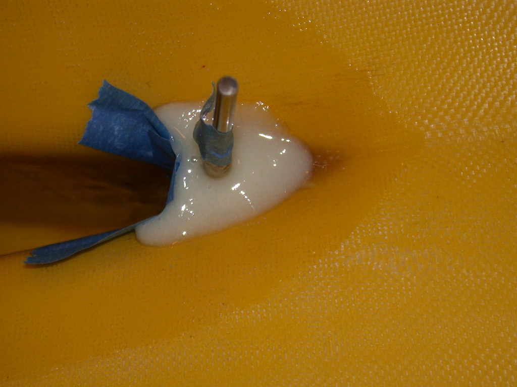
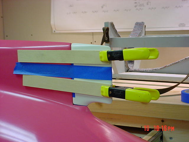
Session two:
The hull builder may have drilled for the rudder. Stand off the leading edge of the rudder with two layers of blue tape and tape with wood stock to the keel inside the fairing and aligned. Dam and pour your resin goop glue around the shaft sleeve. Leave overnight then put the hull away.
Ballasting - Removable
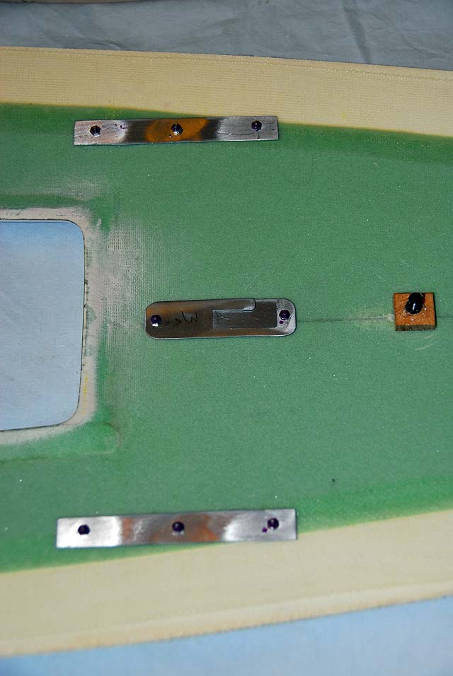
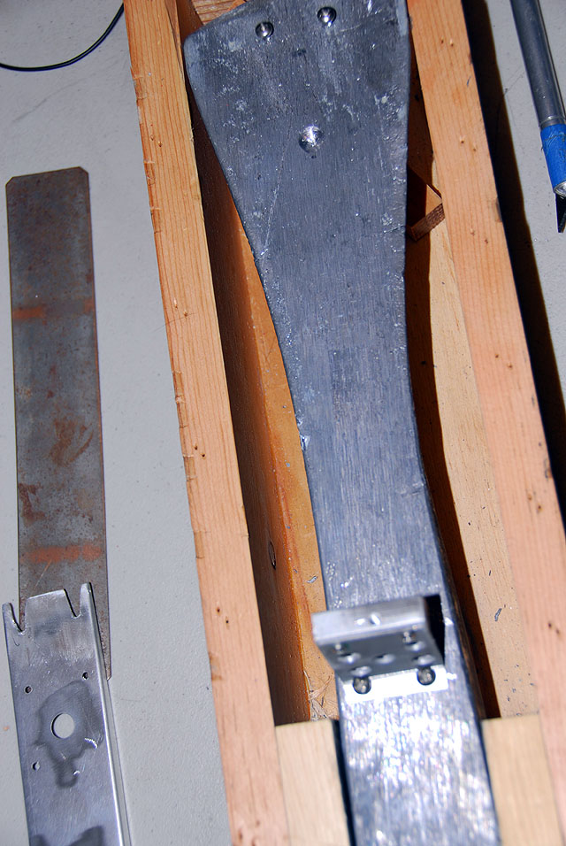
Time think about the relationships. The ballast can have different lengths but will fit only in one place in the keel. The mast of the EC12, placed by the modeler, should fall within a half inch of 25-3/4 on the deck. This spot is supported above deck by a mast step and underneath by a slotted holder for the compression strut.
Now consider where the System Board chassis will be secured to the ballast based on the compression strut dimple in the ballast. You have a 1/2" of play fore and aft. The chassis can also be shortened from the template by an inch. Due to jib line fouling it would not be good to have the chassis overhanging the ballast.
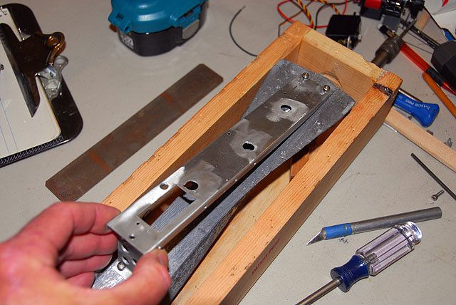
Mark where the chassis will be mounted fore and aft. Check this so the forward end of the chassis will not be restricted by the forward mounting screw of the handle. Install the handle mounts for lifting the ballast. Here a loose handle was chosen using heavy line and tubing. Others have used a custom heavier handle that is removed by one screw on one end and a retainer slot for the other.
Deck Mast Step
The System Board
This is the unit to have for all the reasons stated in the magazine. Moreover, this design is applicable to many different models. It will give you a good gear experience all through a weekend and beyond with no frustrations while playing.
This will take many sessions but goes fairly well if you have all the parts in advance. the plan drawing for the board is available from the class. This is a template for all the attachments and hole drilling. You can also buy the board from two of the class suppliers, RMD and CPM.
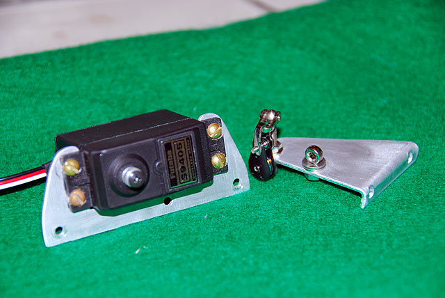
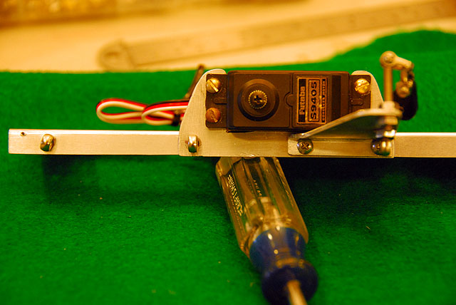
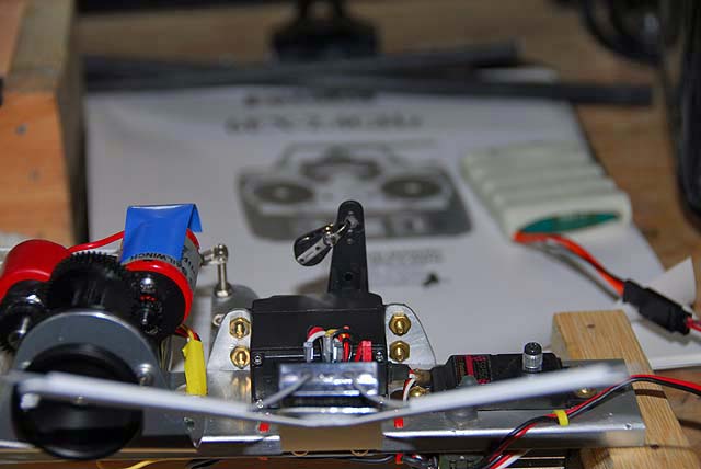
The RMG SmartWinch 280EL is recommended for the EC12. Two servos are needed with 100+ torque. The loads on these servos is demanding so don't go cheap. The digital Futaba S9405 is used for here for the rudder and the S9350 for the jib servo. The old Futaba 6EX 2.4GHz is used here too. The new Futaba 6J has included the modifications we have make to other models; no external antenna, a rotary pot for channel 6 for jib trim and multiple channel servo mixing.
Session One:
If you bought the board chassis complete, you are done here.


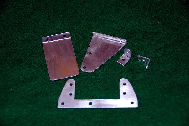

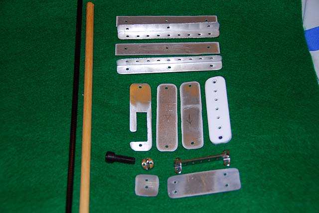
Any chassis design that provides a stable platform for the gear to serve this end should work well for you. The one seen here was designed and built in late 2007 and still in service. The template was updated late 2009.
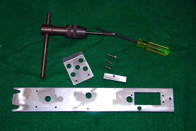
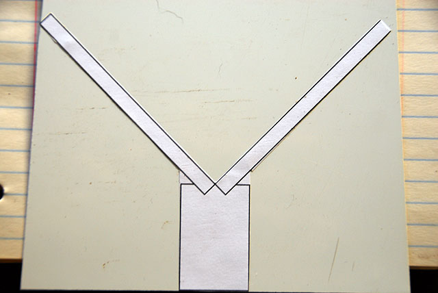
Make copies of the template. Cutout the separate pieces and stick glue them to aluminum. Cut the pieces and drill the holes then clean them up. The drawing shows bending the two sides for torque strength but some have not seen this needed. The stern mount can also be one bended sheet and the the structure you see here. However, you need surface for good purchase of the thumb screw threads.

Session Two:
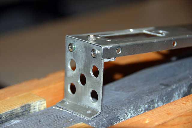
The hole in the chassis for the mast compression strut is the key to the SB's location on the ballast. Mark and install the bow screws in the lead for the chassis slots. Connect the chassis to the stern mount and install the screws to secure it. Drill and tap for the thumb screw.

Session Three:
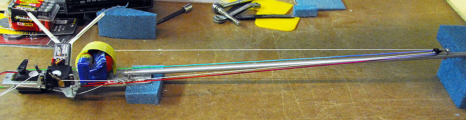
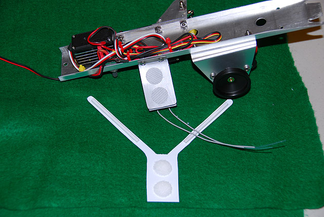
Install the boom mounts on the chassis. the eyebolt is a bungee line guide. Assemble the outrigger post and attach the bungee return block. Install the jib servo on the rack. Attach both to the chassis noting the eyebolts for the main sheet line guides on the chassis and outrigger.

Session Four:
Install the rudder servo and the power switch. Mount the winch and install it to the chassis. Install the blade for the receiver. Make the antenna support with small straws for the two aerials. This is mounted with Velcro when finished and the receiver attached the same way.


Session Five:
Wire the unit and tie it down. Put a line strain tie at the end of the chassis for the power lead to the battery. Stick on the RX and test your work.
Session Six:
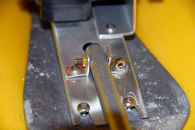
Prepare and install the jib servo arm. Prepare the rudder servo arm, link rod and tiller for the rudder shaft. Nothing special about this part.
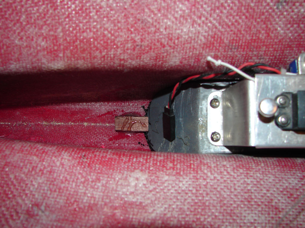
Session Seven:
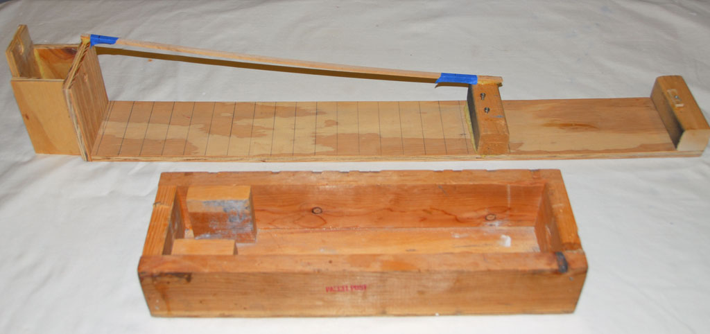
Size the boom to fit snuggle under the bow retention wedge. This can be made from an arrow shaft, wood or carbon fiber. You do not want this to move around to protect the hull. Prepare and install the bow block and mount. Install the boom and connect the chassis to the ballast or the shop rack.


Session Eight:
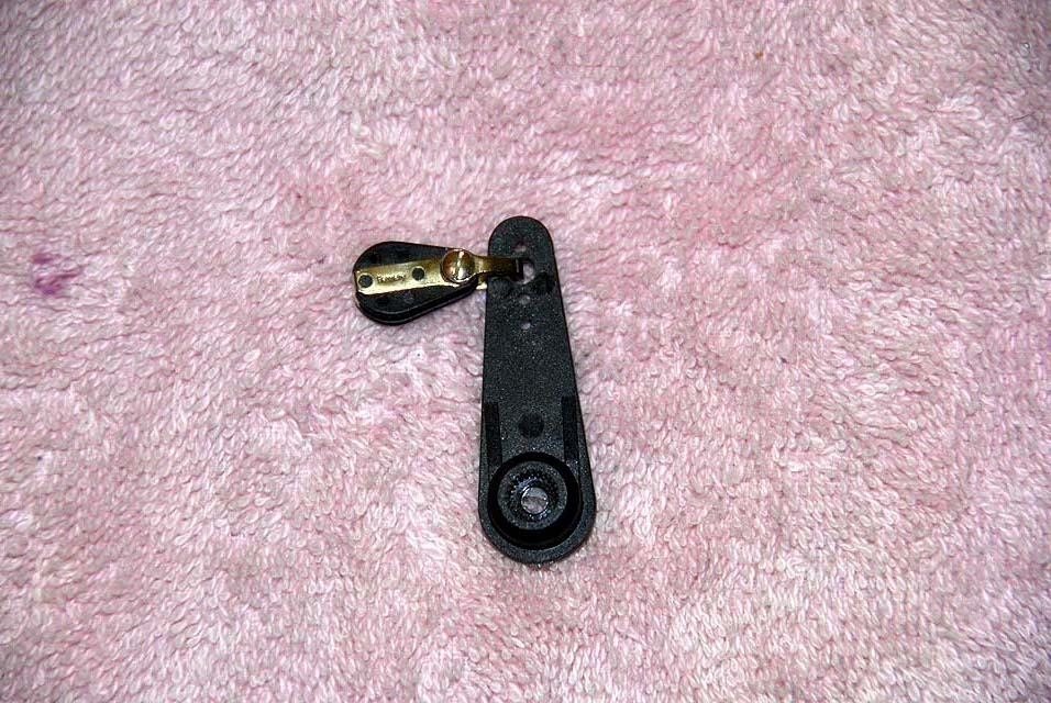
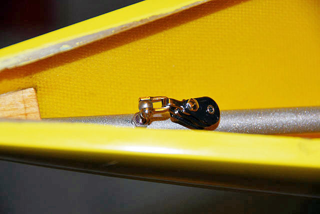
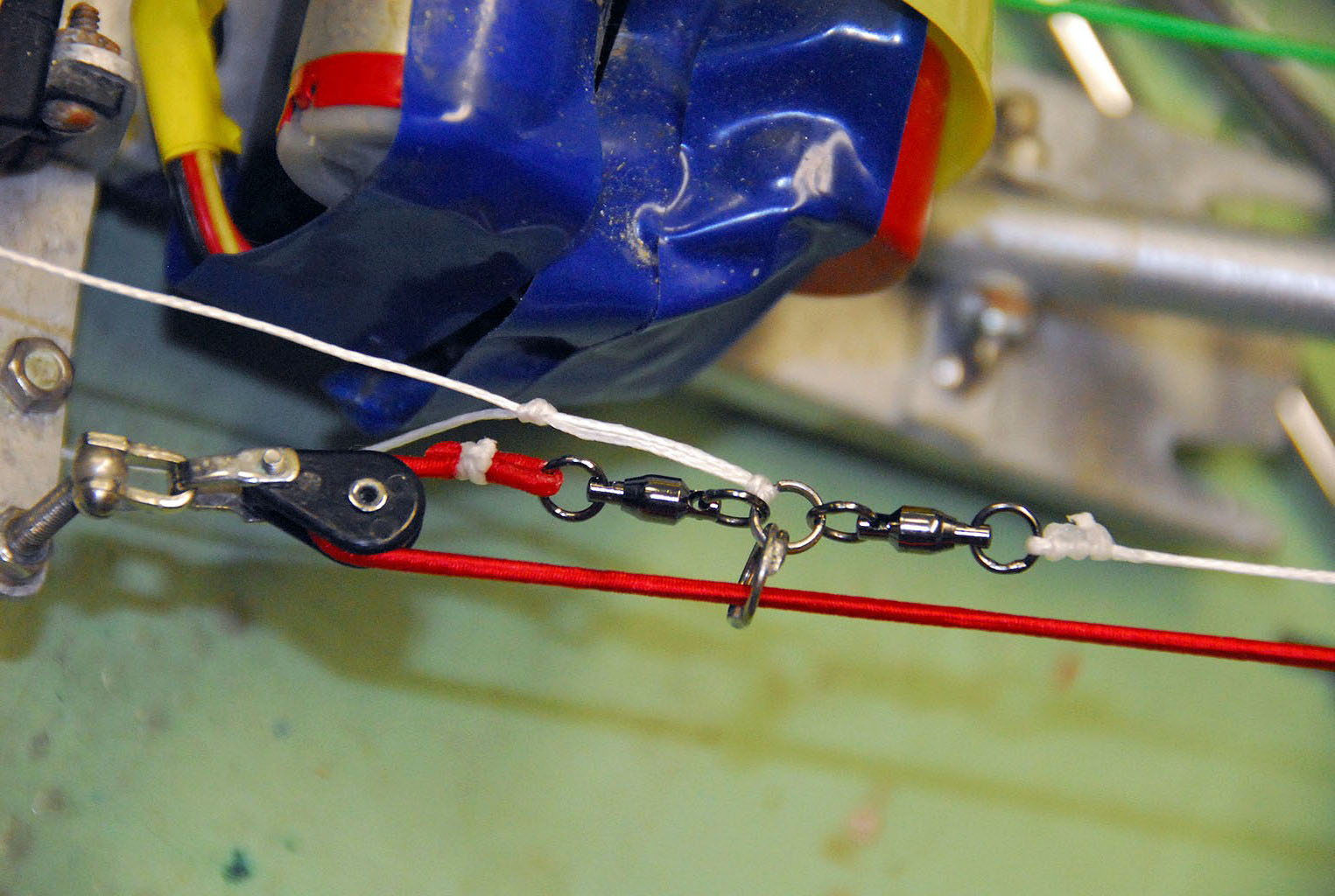
The biggest pain in the beginning of the System Board was the twisting of the winch line. The line twists as it tracks through the block and so does the bungee cord. While swivels were used, it took many variations to arrive at the arrangement you see here. It is rock steady.
These swivels have bearing and TWO are required with soldered split rings. The collector is at the full sheet out position with no turns on the winch drum. During calibration of winch, this will creep forward.
Route the lines along the chassis guide and there will be no fouling. The jib sheet line can be a problem during drifting conditions where the line falls slack to the keel. Make sure there is nothing it can snag on forward of the servo arm. It will not reach the outrigger though.
The two sheetlines are made from one very long doubled line to lessen crowding on the collector ring. They can be sized later when the rig goes up.
Calibrate your settings for the winch and the transmitter. Adjust the bungee when you are done to have just a bit of tension. This will lasts a season with minor adjustments.
A thin sheet of CF is stuck on the receiver for water protection when removing the hatch cover.
I carry a 16" piece of .012 wire doubled and creased to fit through a fairlead for threading the sheetlines quickly. This also has swage at the end so it will not fall through fairlead when you turn loose of it.
You might also give some thought to building a spare System Board for major competition travels. This can be calibrated and sized for your rigs at home. Then if something that will take some time to repair happens, you can swap units in about 5 minutes with no adjustments needed.
Finish
Install the hardware on the molded deck. Size the sheer of the hull and glue on the deck.
Build and raise the rig.