Nickel Silver Rings
![]()
![]()
![]()
![]()
![]()
|
Nickel Silver Rings
|
|
Last update, January 20, 2002 This is an archive page Process is no longer used as we have left round booms behind.
Nickel Silver Controls, Guides and Line Terminals
The first boat built at DMYC had rings, clips and clew hooks for adjusters and line guides made from nickel silver wire. The idea came from the drawings in the EC12 manuals published by Ragged Symmetry. These were fashioned from the drawings by one of our group at much labor and cost. Now with the building of a J-Class boat the project is revived with the need for these pieces but in a larger form. The process has been documented for this website, as the size is not the question. Labor has been greatly reduced with slight changes in design and some different tools.
Why would one want to use these pieces for sail rigging? They are strong and hold their position beyond failure of what they are connected to. They can be adjusted with one hand while the boat is in the water. Adjustments are positive and can be minute. They are low in line friction and aerodynamic drag. Once made, they are an inventory part and can be moved from rig to rig. No other parts are needed like hooks, snaps, screws and bowsies.
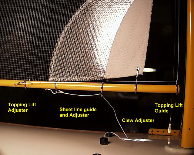
Uses: Main Boom; clew and sheet line guides and their adjusters. Jib Boom; forestay mount, adjusters for the downhaul, topping lift, clew, mast rake and sheet lines, line guides for the topping lift, jib swivel and the sheet line. All line guides are adjustable as well.
Cost: The three materials needed are expensive for silver soldering for just one boat. Silver compound solder, silver flux and 14 gauge nickel silver wire can cost $70 (USD2003). It was done here in a club effort for eight boats over time, as 13 to 14 pieces are needed for one rig. It is an economic thing, so work it out.
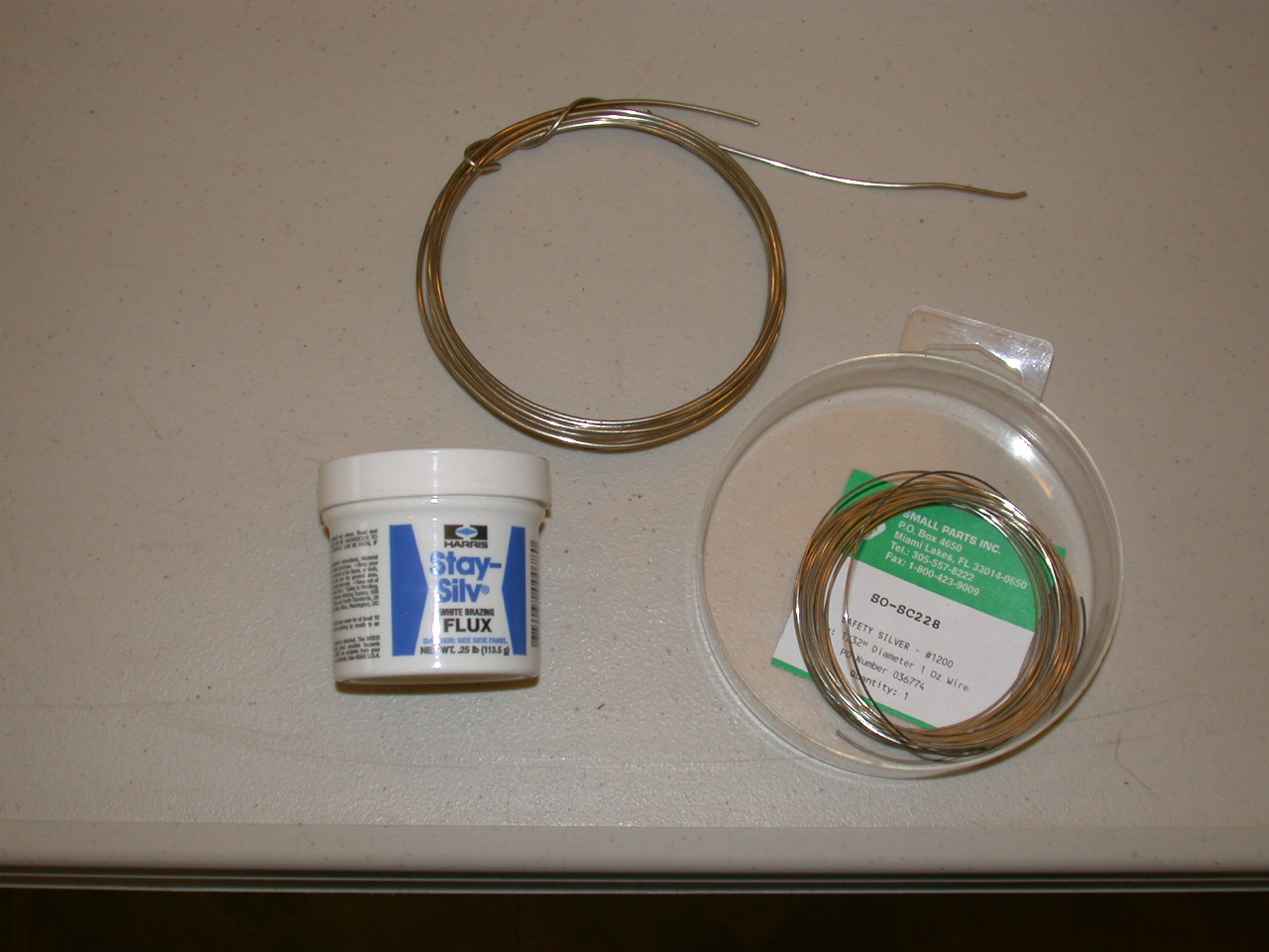
Materials and Tools 14 gauge nickel silver wire comes in a ten foot coil, enough for about 80 pieces. The flux and solder is a lifetime supply. So, put this stuff away in a Ziploc for another time when you are done.
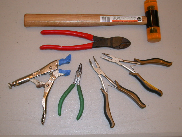
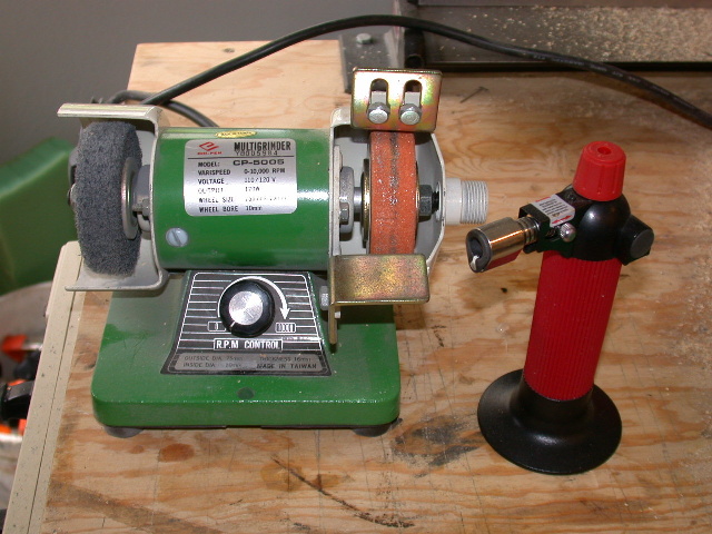
Don’t skimp on the torch. The little one you use for shrink tube electrical will work in time but is inconvenient and temperamental. A chef’s torch is 40 to 60 dollars and will serve you well in other things. It will sit flat on the bench when running, which will free a hand and uses the standard aerosol cigarette lighter butane injection loading system.
Two other specialties are a non-ferrous hammer and a pair of rounded jaw pliers. The hammer shown here is larger than needed but was cheap and does the job without marking the wire. The pliers are from Small Parts, Inc., and allow bending the wire without creasing or marking the wire. The other pliers shown are for light bending and handling the piece while you are working it. The 5” Visegrip is the same used for crimping shroud wire sleeves and is used here to form a connecting node on the rings. The jaws need to be taped to protect the wire.
Note: It has been found that if the solder is applied correctly, meaning that it flows evenly over the well heated wire, it will fill nicks and marks on the wire. When buffed, this will reduce fraying of attached or pass through lines.
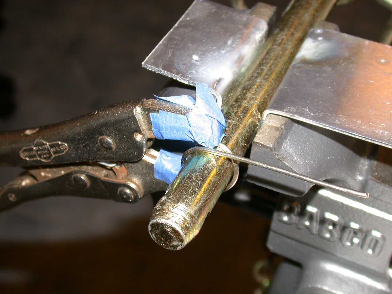
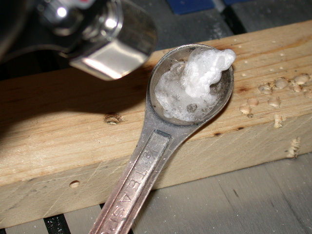
Some scrap aluminum was used to form a shield in the jaws of the bench vise. A small kitchen measuring spoon was found to be handy for melting the rock hard flux.
The major tool improvising needed is a forming rod. This is to be slightly larger than the boom to be used. A bit of testing will be needed to determine a suitable size rod. The reason for this is that a larger ring is needed than that which will fit on the boom. From this, the larger ring will be formed to have a bump (connecting node) that is the action end of the ring. The finding of a rod diameter that will produce the node desired is key to the process and a repetitive production. However, close is good enough, as the wire can be cut long or shorter than the forming rod to get the same result. A clevis pin was found here in a junk box. This will be explained more later.
The Process Find a forming rod that will work to produce the node size that is liked. Testing is all that can be offered here. Form a ring, file or grind a flat end to the wire. Flux and solder the joint. Place the ring on a boom size model and form the node. Buff till an even pewter look.
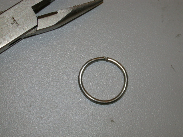
Forming the Wire It is easier to work with about 6” of wire than the whole coil. The wire may need straightening from being in the coil or just handling. This is easy to do with the hammer on the vise table. Be gentle, the wire is quite malleable.
File or grind flat the working end of the wire. Place that end onto the forming rod and gently tap it with the hammer to the roundness of the rod. Now gently hold the end to the rod with the padded jaws of Visegrips and wrap the wire around the rod to just past the starting end. Release the end and slide the wrap off the forming rod. Cut the wire just before where it meets the starting end. File or grind flat that end. If you use a mini grinder or a Dremel, the ring can be twisted sideways slightly to access it.
Now work the ends with the rounded pliers till they will meet in the arc of a ring. With fingers, compress the ring so the ends will overlap a bit then open them so they will spring together by tension. Some minor twisting may be needed so they will come together aligned.
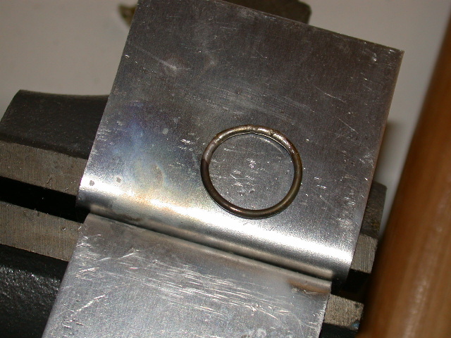
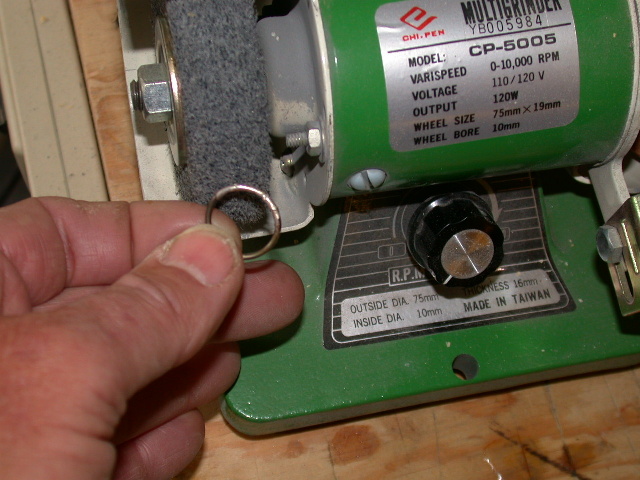
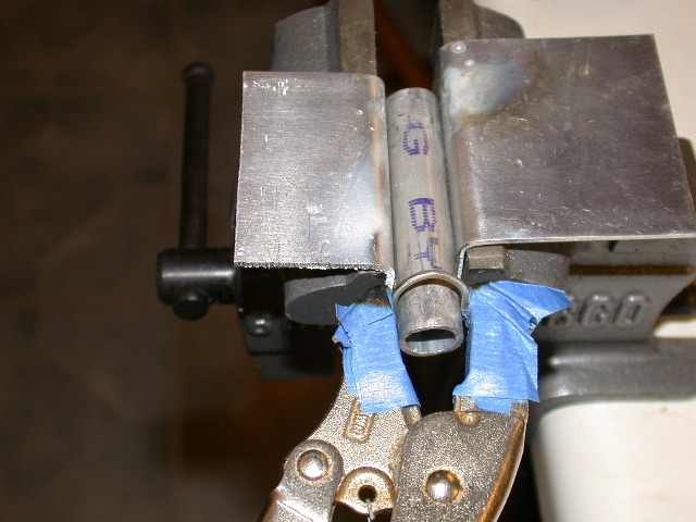
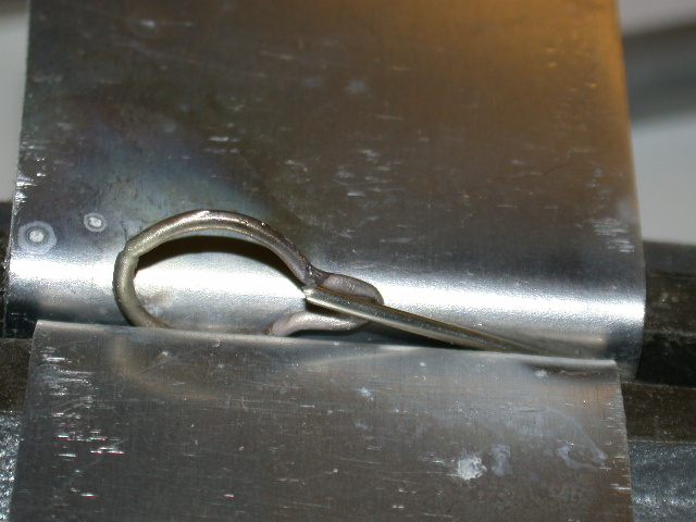
Solder the Ring Heat a bit of flux till it bubbles with the torch and dip the ring connection to coat it. Once on the ring it can be reheated to flow if needed. Here the ring is placed in a protected vise, heated and the solder applied. One could do the same with the torch sitting on the bench, holding the ring with pliers and apply the solder. Steadiness is a reason of choice. The wire needs to be hot and the solder will flow and penetrate when a shiny silver. Remove the wire with pliers and heat again to sharply shake off excess solder and flux. Cool the ring on a metal sheet or dip in water. When ready, buff the ring with a light abrasive fabric wheel on a grinder or Dremel. The black that is seen is from the flux and comes off easily. The whole ring will take on a look of pewter.
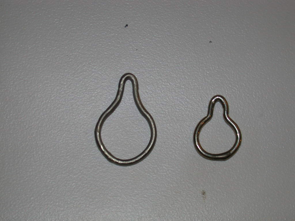
Note: The initial wire wrap can be cut long or short of the starting end to adjust the size of the connecting node. Small nodes are good for line guides or anchor points like the forestay. A larger node is good for attaching the clip for line adjusters where the line can be removed like for the sheets. Take mental note of the cuts and the results toward a desired size.
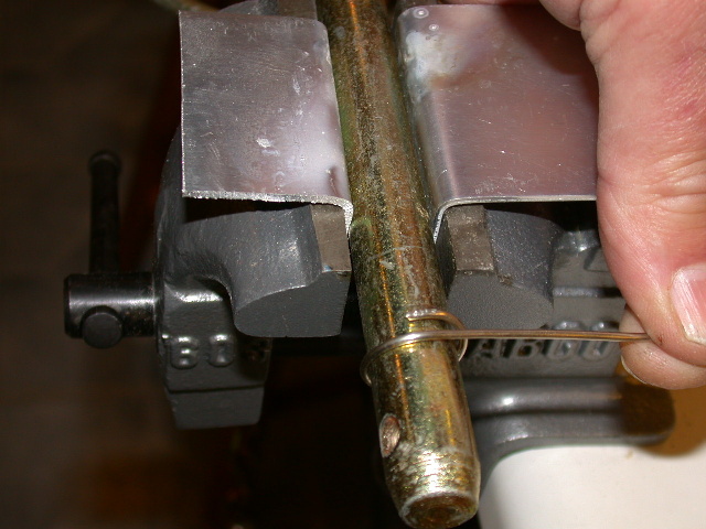
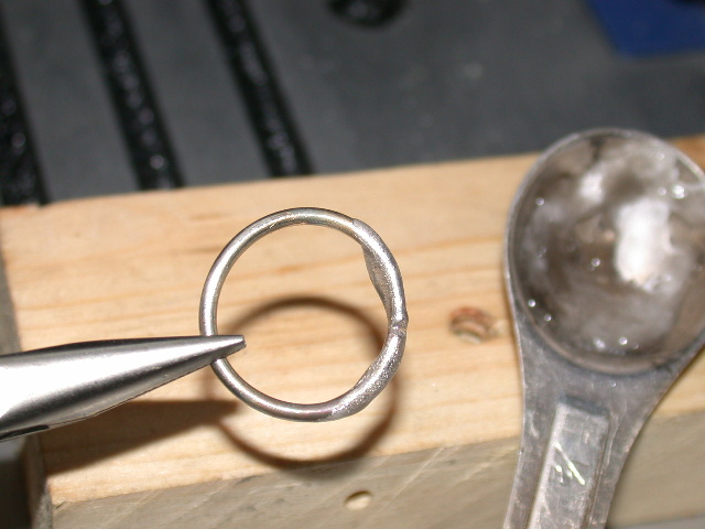
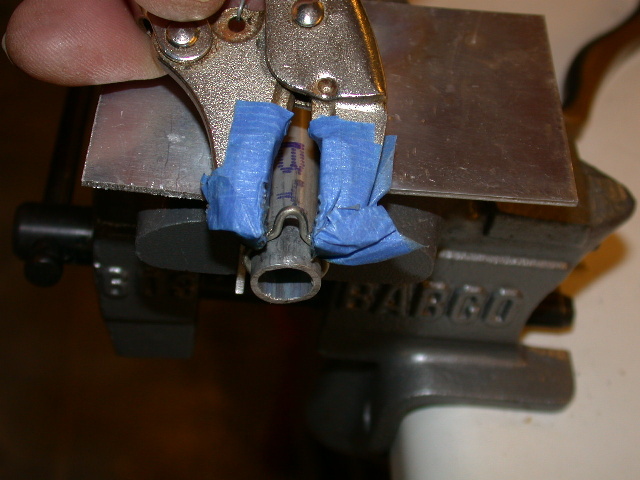
Forming the Connecting Node Place a sample of your boom in the vise. Hold the ring on the boom with the solder point at the bottom. Gently close the sides to the boom with Visegrips. Then work up the sides till the ring has closed to the boom at 10 and 2 o’clock. (The jaws will close at 10 and 4 and at 2 and 8 positions on the clock.) Now squeeze the node from both sides to close it further to form the shape seen in the photo. Gently work from both sides so you will have even curves. Remove the ring, inspect for nicks and buff if needed. You’re done!
Adjusting and How They Work A properly formed and tensioned ring is designed to slide on the boom when perfectly adjacent to the boom. When off that line the size of the ring becomes small in presentation to the form of the boom. It will jam and with continuing tension attached to the node will lock. However, with just two fingers, the lock can be broken and the ring can be rocked side to side and moved to another location. Push the node in the direction of the tension and it will lock again.
If an adjustment is needed when the boat is in the water, all that is needed is to reach the adjuster with one hand. The fingers can feel minute movement.
When the ring is formed onto the sample boom the first time, it may be too tight to remove. Place the rounded pliers over the node at right angles to the boom and gently twist a bit sideways. This will slightly spread the ring open so that it can be moved as designed. Likewise, if the ring becomes loose, the node can be squeezed a bit to tighten up the fit.
Planishing This technique will strengthen malleable metal. The process is nothing more than laying the piece on the flat vise table and tapping the ring with the hammer. Turn it over and do some more. Much of this has not been needed. If you see the node bending in the direction of the tension, some planishing will be needed. Likewise, if a ring consistently loosens on the boom during sailing, planishing will be needed.
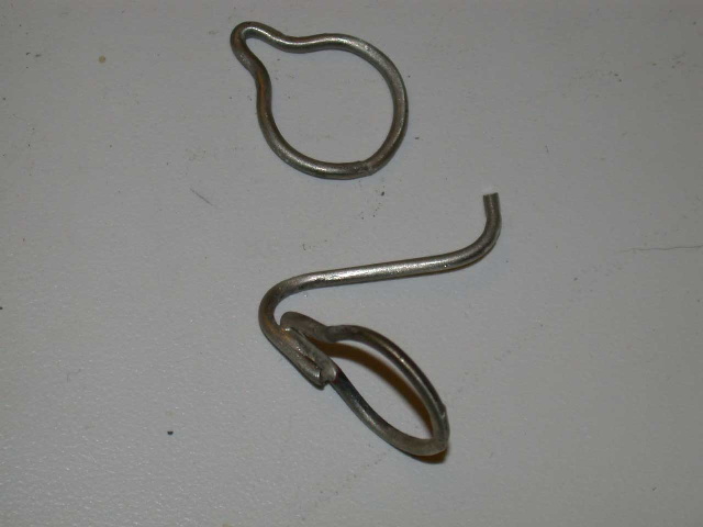
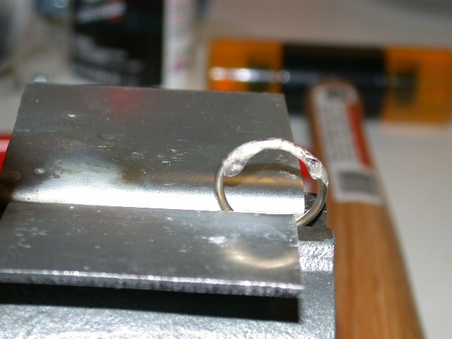
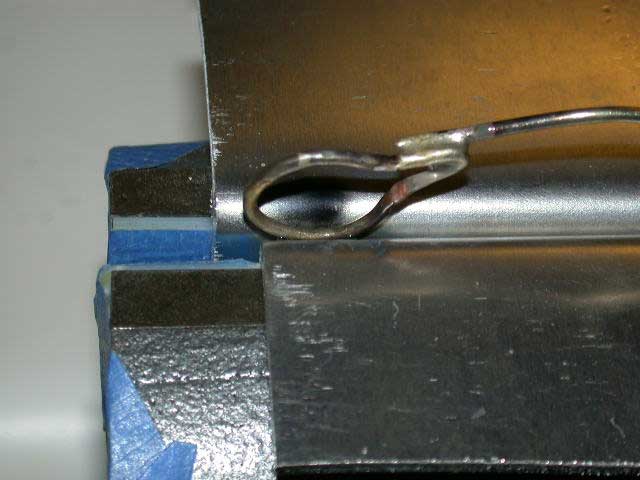
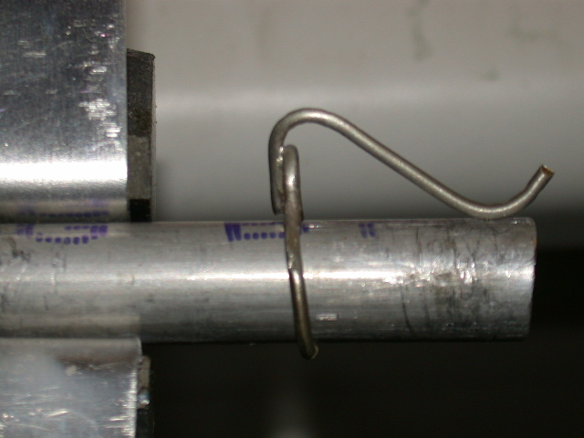
The Ring Clip The clip, shown here soldered to a ring, does nothing to the function of the ring but provide a secure holder for removable lines. These are the sheet lines and the topping lift bungee with a small loop on the terminal end. By not using snaps and CL connectors, there is less likely for failure, less aerodynamic drag and handling convenience is greatly improved.
A piece of wire is cut to the approximant length of the clip and bent slightly in an arc. Melt flux onto the node of a ring and one end of the wire. Place the ring in the vise at an angle. Position the wire in the vise so it will hold one the flux end along the node on the ring. The vise is just to lightly hold these pieces. Heat the parts and flow on a small amount of solder; a lot is not needed. Cool and buff the ring and clip.
Bend the wire sharply over the node then gently down to where it will touch the boom then up a bit to receive the line. Test it on a sample boom. Note that line tension on the ring will run away from the clip so that the ring will rock in that direction slightly to lock in place. The loop in the line slips on easily and seeks a level near the node under tension. Piece of cake!
Production Once a few have been made a production line can be set up. 1. Wrap and cut. 2. File or grind the ends flat. 3. Arc and align the ends into a ring. 4. Flux. 5. Solder. 6. Buff. 7. Form the ring to the boom and make the node. It takes 10 minutes to complete a ring, done individually, after the first couple. And, it is not intensive work.
A few of the rings in place on the booms can be seen in the Rigging sections. It may be noted that they are shiny silver in color. The first inventory of these pieces were taken to a jeweler to have the blacken areas cleaned in a solution and the pieces buffed for added luster. That expense was not afforded in this round of production for the J-Class Shamrock V. The fabric abrasive wheel cleans the ring and creates an even dull gray finish that appears just fine.
Documentation of the production of a J-Class Shamrock V, from scratch, is currently underway in the building section at www.deltamyc.com.
|