Radio Mods
![]()
![]()
|
Radio Mods
|
|
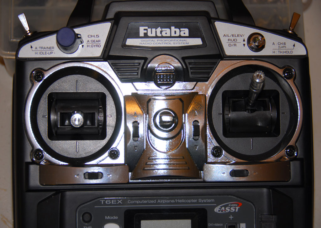
Last update, December 27, 2007 Modifications to Futaba T6EX 2.4GHz Not completed
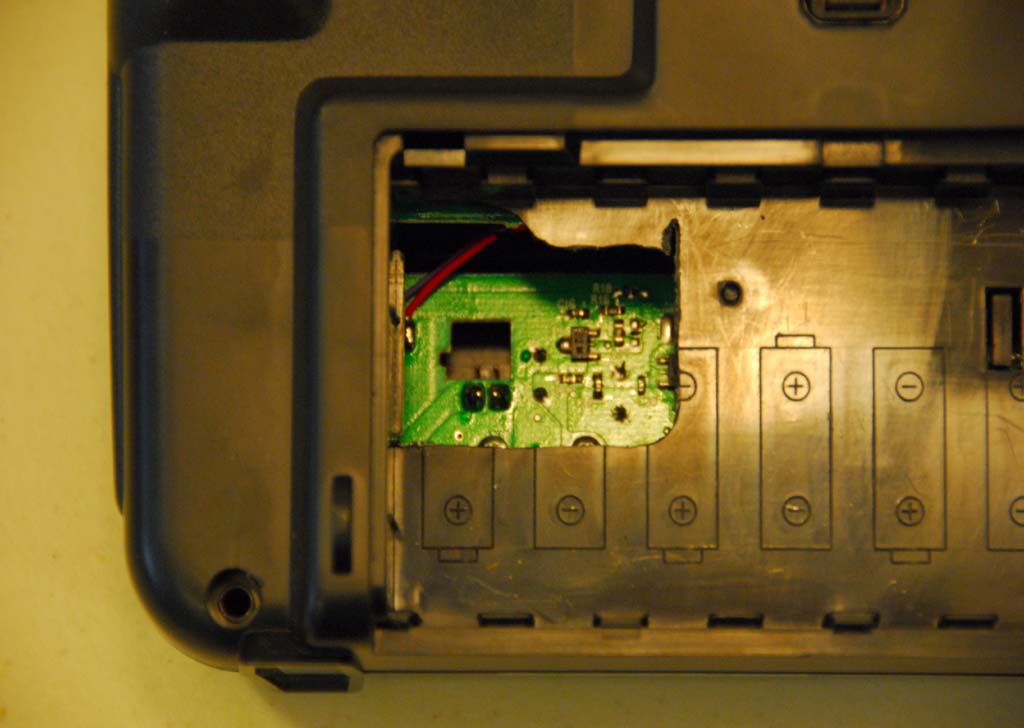
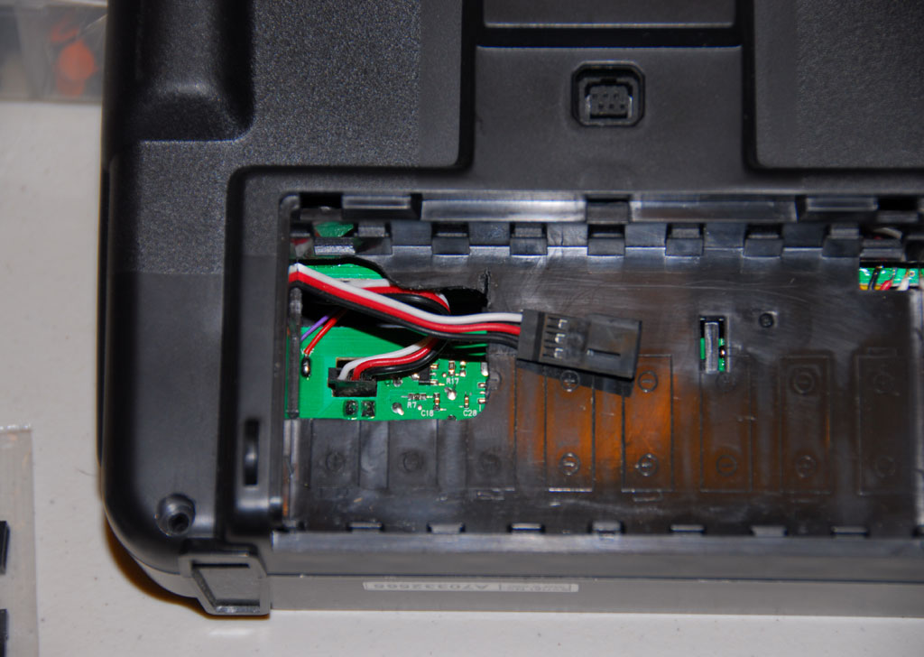
The Battery Compartment: Futaba has finally placed the battery plug-in where you can see it and it is removable. However, the opening is the size of a dime and you next small pliers to deal with it. Not good!
Remover the case and use a Dremel to enlarge the area like you see here. Place a short servo extension into the radio board that will connect to the battery.
They have also not dealt with the thickness of some shrink wrap. Work this out but be careful not to break the tabs on the battery compartment door.
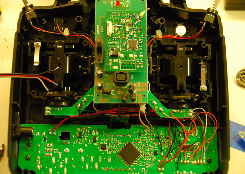
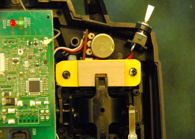
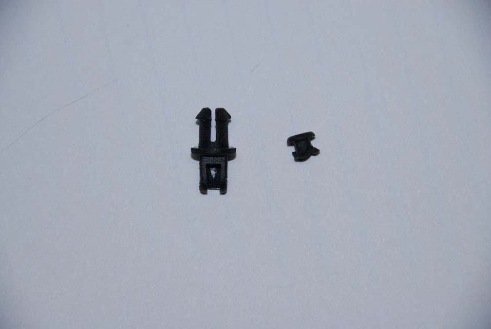
Jib Trim The toughest issue is jib trim. Some will install a knob to a pot and others will make the change to using one of the two stick functions we do not generally use. Here the latter will be done to the elevator function (vertical function of the right stick). This has an unused ratchet surfaced form where a wiper can be installed. Remove the tension spring from the gimbal. This would give the vertical motion feel and stability. The elevator and wiper is shown on the left.
The Knob Mod Parts and Tools: 5k Potentiometer - 15mm or 5/8" diameter to fit in location shown here. 26 gauge wire Soldering stuff including a de-solder vacuum - Radio Shack Knob is from Radio Shack
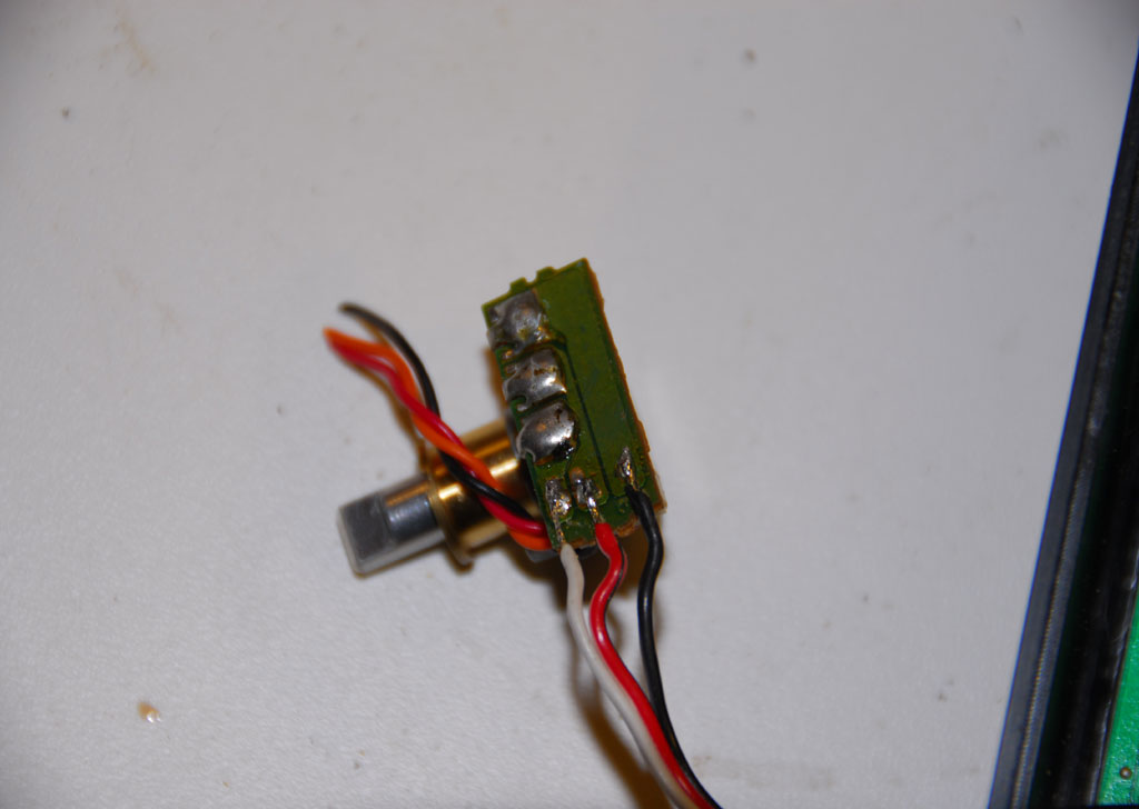
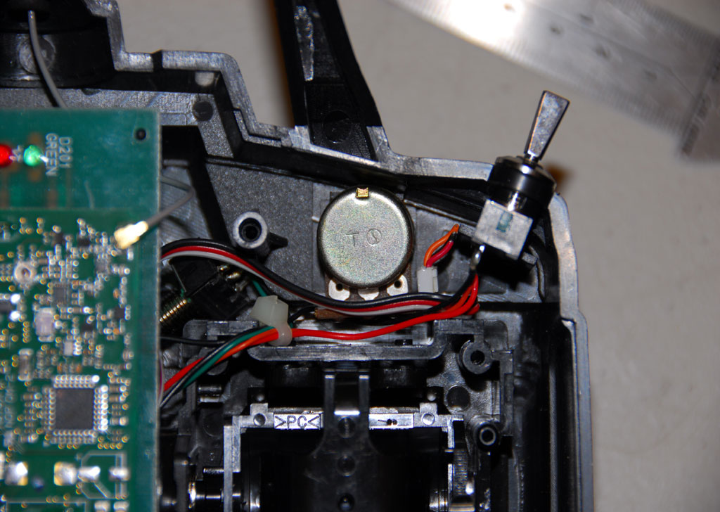
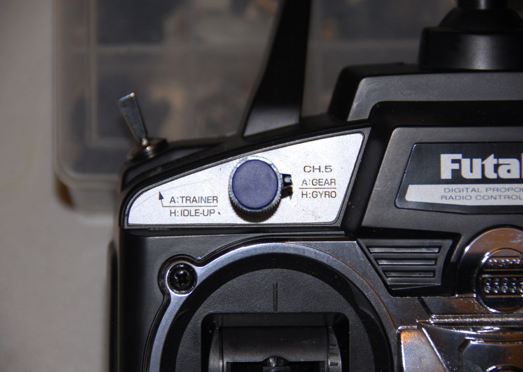
The gear retract switch was removed and stored in the case. This location for the knob is the same as used on the old Futaba 6XAS and easy access for the left fore finger. The 5k pot shown here is Futaba salvage parts from the shop bin. It has a small circuit board connection point whereas, a store bought one will have solder pins. Black/red/white ribbon wire was used. Colors do not matter, as long as you attach to the pot points in the same order in both locations.
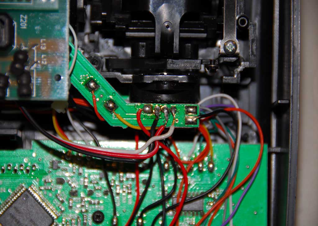
The left stick horizontal function (airplane rudder) was chosen and the wire solder points are the three pins to the right of the red wire on the circuit board below the gimbal. This is tight soldering so be careful that one does not touch the other pin. When all is soldered route the wire and pot to the hole. You may need to drill out the hole to fit. The stick gimbal was locked into place by the mod you see above. This was to prevent inadvertent trim movement when the winch stick was moved for the winch. Bracing is needed and close tolerance is suggested. You'll figure it out.
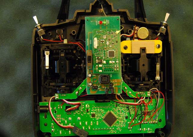
The Antenna The Spread Spectrum radios have flimsy folded antennas that can pop off the mount when bumped. No big deal but it takes 5 minutes to get it back on. This is not good when in a race and the antenna wire is working side to side as you jostle along. Some Swedes thought of the obvious...get rid of it...and stored it inside the case. The boys in South Florida tested it locally then in large fleet regattas and found no change in signal strength or response. Here is the modification to the Futaba 6EX and 10 minutes later I was out of the shop.
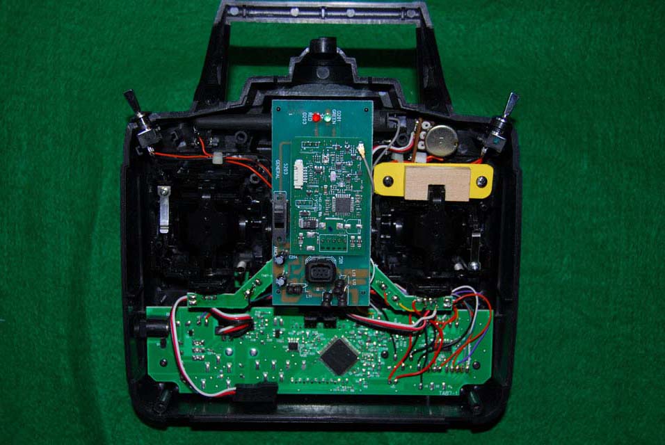
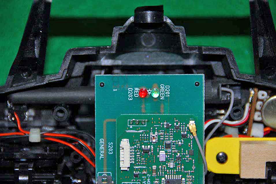
Obviously, the caution is not to damage anything, as antennas and the lead wire are fragile. Open the cast and lift the antenna wire plug off the RF board with a razor knife. It is a press fit and swivels and seen here to the right of the green light with a gray wire. The antenna mount to the case is one of those damn multiple press tabs that go on well but a &%#$ to get off with one hand. Once it is released you can lift the antenna off the case with the wire trailing. Pull the rubber grommet out of the mount and carefully push the swivel connector through to free the wire. I suggest you not pull it through. Now the mount can be passed from the wire. Press the plastic tabs on the mount to release the pins that allow it to swivel. This is not fun...where do they find these designers? Once you have the mount off the antenna you are home free. Lift the RF board and place the antenna across the case above the case screw mounts with the base toward the pot installed for the jib trim. Press the antenna wire connector back onto the RF board from where it came.
Reinstall the case and you are outta here. Love it! |