Rudder
![]()
![]()
|
Rudder
|
|
Last update, December 1, 2009 Rudder Installation
Preparation Lighten up! The rudder installation is simpler than you think. This is a long section but it condenses quite a bit. If you have all the stuff above made, you will be out of here in less than thirty minutes just in time to watch Sopranos re-run.
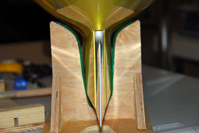
This may have been done during the hull preparation and cleaning. Lets go over it again. The hull fairing area should be inspected to be smooth and conforms with the rudder leading edge. The flat area of the hull, where the rudder hilt fits, should also be checked and smoothed. This whole fairing area is a rough place for the hull manufacturer to work with in the half hull mating procedure. Minor work is often needed.
The manufacturers that use a single molded hull seem to have a cleaner rudder fairing but too should be checked. The certified class molds produce a standard rudder fairing now that is a one-half inch radius evenly from the keel bottom to the hilt. Some manufacturers will pilot drill for the rudder shaft so that the finish drilling can be done from inside the hull, not needing very long drill bits.
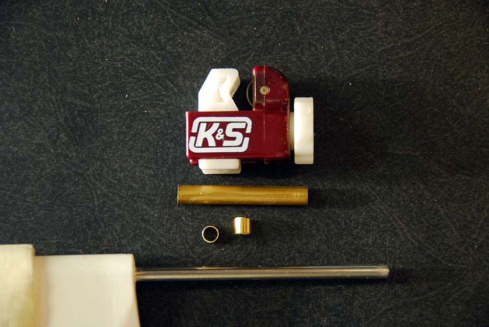
Manufacturers also use different size rudder shafts and they are usually Stainless Steel. This will need to be checked so you will have the right tubing for the process. Most manufacturers provide a sleeve for the rudder shaft. We recommend using the grease seal regardless to the outer tube height.
Please read through this to be familiar with the process. When you are ready to pour the resin mix for the installation, pause and think it through. Make sure the rudder is resting free in the fairing without stress. Make it so. It will then go quick, is final and will be done right.
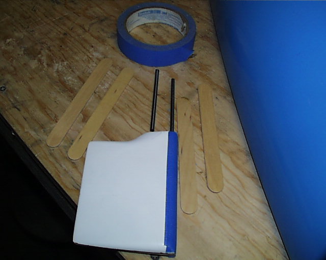
Installation Process Clean the rudder shaft with a bit of Emory cloth and then mark the height of the outer tubing sleeve with a pencil. Put a dab of CA glue at the base of the shaft and slide a bearing tube over it using a needle file to urge it along. Do the same with the upper bearing stopping it with the pencil mark above the bearing. Let it dry thoroughly.
With the current hull mold you do not need a layer of tape on the leading edge of the rudder for a spacer. If the fairing has been cleaned with a 1/2" dowel or the like and light sandpaper, the rudder will rotate there will with the heavier servos. This is mention for it is a departure from previous postings.
If you do not have a pre-drilled hole for the rudder shaft: Mark where the rudder shaft hole will be. This is generally 3/16" to 1/4" from inside the fairing. From the outside drill a small pilot hole. Be careful with the chuck of the drill not to mar the fairing. If you cannot drill straight down, carefully drill at an angle. Then drill straight down from inside the hull with a bit size the same as the rudder shaft. Slip the rudder in from the fairing side with just the shaft. Trim the hole from the inside of the hull till the shaft fits with the rudder snug against the fairing all the way down to the keel. Test is again with the tube over the bearings and trim to fit. If you have the 3/16" shaft the hole will end up a loose 1/4". Rough up the sleeve with some Emory cloth and set it aside. Take a moment and look it over good.
If you have a pre-drilled hole: What size is the hole? the one here arrived with a hole the size of the shaft. That is okay though for it is the guide you can use for drilling from the inside. First see what the alignment will be. Put the shaft into the hole and see how the rudder aligns in the fairing. Work the hole with the drill till it is straight with the fairing. Then drill with phasing bits to 1/4 inch. Test and size with the same bit till the outer sleeve till fits.
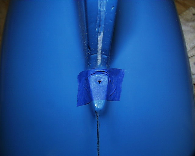
Remove the rudder and sleeve. Put a small slit in the tape with the razor knife so the outer sleeve will pass through it easily. This should prevent oozing of the resin later. Put some polishing wax on the hilt of the rudder or any mold release agent to prevent stray resin from permanently cementing the rudder to the boat. A thin layer of Vaseline will work too. Most use two layers of blue tape on the leading edge to give the rudder some wiggle room inside the fairing when all is cured.
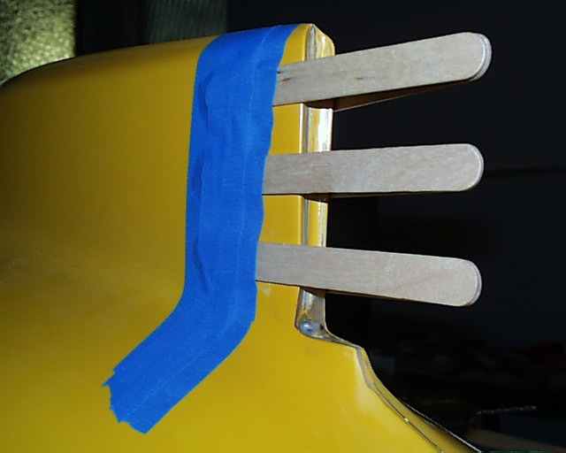
Four tongue depressors are taped to the rudder. This is now placed over the keel and the shaft/sleeve into the hole. Check alignment one more time. Then, holding the rudder snug in the fairing and snug at the hilt to the hull, tape the extended depressors to the keel. Once it is free of your hands, check it again. Then carefully apply tape more generously if needed.
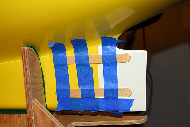
Inside you can use blue tape as a dam for the resin mix here, as it will not be that much. Place tape horizontally and then vertically for strength and make it straight for looks. Pause...think it over...
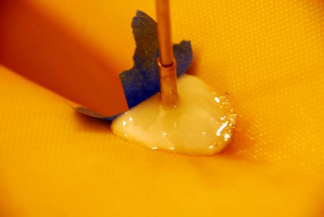
Mix the resin with fiber thickener (did you read Adhesives for the Goop.) and scrape it out of the cup to around the outer shaft until you have about a 1/4" to 3/8" covering the outer sleeve. Let it cure overnight.
Note: If for any reason you need to move the rudder after the resin is poured make sure the shaft and the sleeve move as one piece. If any resin gets into the sleeve and cures, the rudder is history. Also make sure all surfaces have been cleaned with Acetone or MEK.
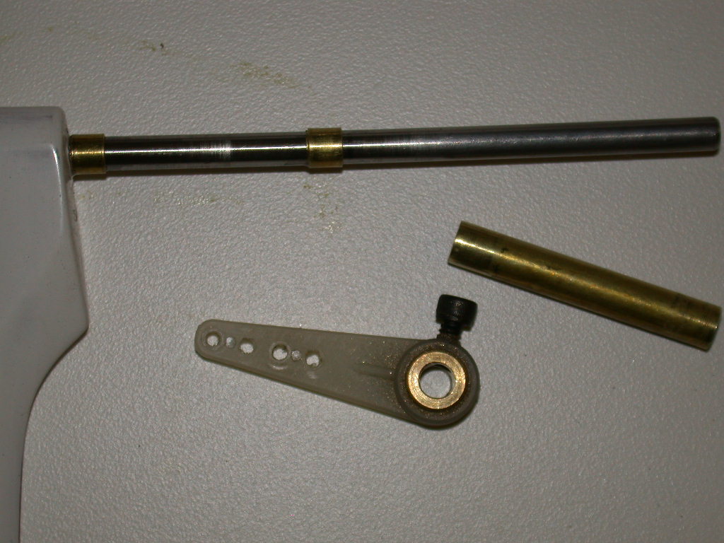
Note: The Dubro 155 steering arm has a inserted collar to fit the 5/32" rudder shafts. If your rudder shaft is 3/16" a #12 drill bit will be needed to enlarge the hole. A 3/16" bit can be used with a bit of wiggling during the drill.
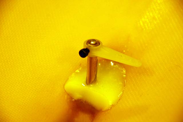
While the rudder is still on the hull slip the tiller over the shaft and down to the outer 1/4" tubing. Mark just above the tiller with a needle file where you would like to cut off the excess shaft. Remove the rudder from the hull, cut it off and then clean up the edge to smooth it out.
Flattening of the rudder shaft with a slight scoring of a needle file is your option. If you are not comfortable with this, pass it up. Retightening of the rudder is an ongoing thing when sailing. The same with checking alignment. Some rudders are hollow and will float if it comes of in the water. If this happens, sheet out the sails and inform the Race Director that you are an obstruction. Sit down and have a Kool-Aid.
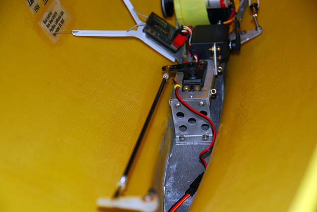
What is liked about the linkage below is that if the rudder is hit it will not slip far off the centered setting. If the rudder is stressed more than that the clevis will pop off the tiller. So, if the rudder becomes loose during handling, check the linkage clevis connector to the tiller first. It most likely will be as simple as that.
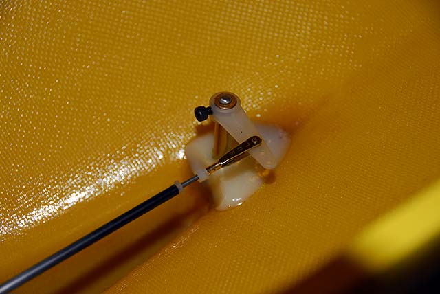
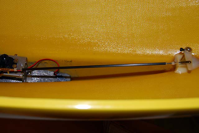
There are many ways to do this. This is the DMYC method. The linkage is made up of two each, clevises, 2-56 threaded rods, nylon locking nuts and a carbon fiber tube. Pack the center section of the rudder shaft with Plumbers Silicon Grease or a Lithium dielectric grease. Install and tape the rudder to centerline the way you did when it was installed. Put the tiller on the rudder shaft point to port. Eyeball the alignment and tighten the set screw.
Delta uses nylon nuts for this sort of thing. Take a 45 mm piece of 2-56 all thread, put on a nut and then thread a clevis and lock nut on the threads. Set the nut that will be at the extension at about 22 mm. This will allow about an inch in the rod to be glued. Mix a dab of 5-minute epoxy, put on the treads and slip it onto the rod up to the nut. Let it cure till your stick sets in the pill cup.
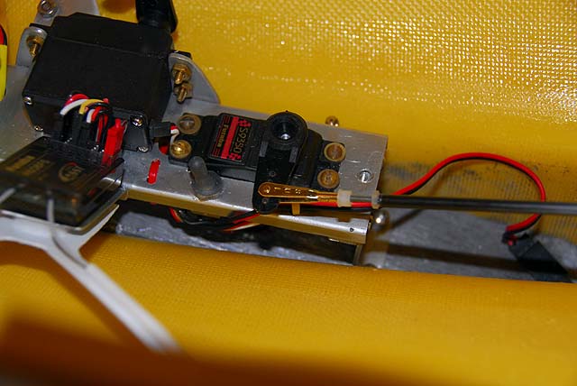
Turn on the radio and install an arm on the rudder servo pointing to port. Do not over drill the holes in the arm. You want the clevis to fit tight so there is no slop. Clip it on and measure from the hole to the rod behind the nut. With this information measure from the tiller arm hole for where the rod will be cut. Both ends are going to look the same. AH! You noticed tension because of the angle. Cool it. It will be alright.
Assemble the other end now like the first and let it set up.
Install the rudder linkage rod and make the adjustments on the clevis ends so there is no buzzing at the servo. When satisfied remove tape from the rudder and check it from the back. Get the tiller very close and then trim the rest if you need to.
Note: With the rudder tiller firmly installed move the rudder side to side and up against the outer fairing wall. Carefully now, you do not want to crack the delicate gel coat. What you are looking for is that the rudder travels fully smoothly and without any binding. Binding will be like a bump in the road and smooth out after passing. This is generally caused by a change in the wall surface near the hilt of the rudder and in the fairing wall. If this happens and you have smoothed the fairing in this process you will have to find the bump and smooth it out. There is a link at the top of the page for the process.
That is it! With the exception of the sheet lines themselves the interior is done.
Heavy Weather There is additional information in the Heavy Weather page regarding more powerful rudder servos, tillers and linkage clevis locks. Frankly, everything that has been done here has served well in high winds.
In The Field A light duty grease is often needed to prevent water leaking into the hull. We use a Lithium dielectric grease. This works good in the hotter climes. One of our members picked it up at a Honda dealership. If you are using the rudder installation with the bearing seals a plumber's silicon grease will work nicely.
|