Board Mount
![]()
![]()
![]()
![]()
![]()
|
Board Mount
|
|
Last update, December 6, 2007
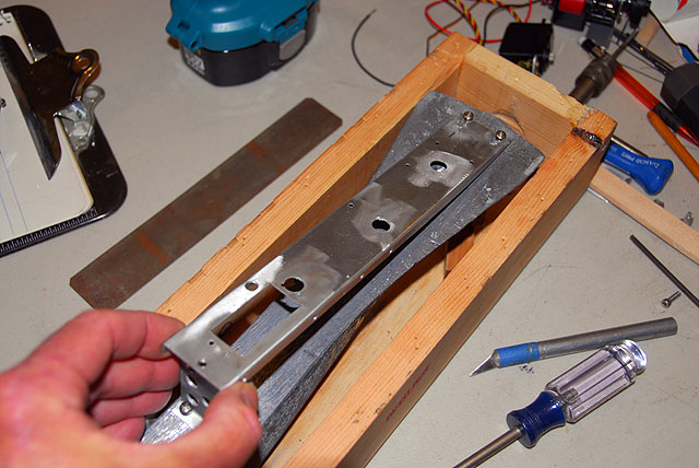
Boat System Platform Mount
Parts: .064" - Aluminum sheet 10"x4", hobby shop or Online Metals, stock item Square stock aluminum SS Machine Screws and Nuts - 4-40 works, stock item SS Sheet Metal Screws for into ballast Tools: Scroll saw Files Dremel buffer Brake Sharp Punch Drill Threading tap
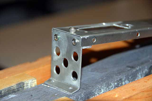
The Upright "Hey Vern, we already checked out the height. Trust me!" Cutout from the drawing or a piece of paper 36 x 50mm. The top and bottom sections are 10mm and the lightening holes are the same. Glue stick this to .064" sheet just like you did in the previous section. Cut the sheet, punch and drill the four points for 4-40 screw size and use several sizes to make the larger holes.
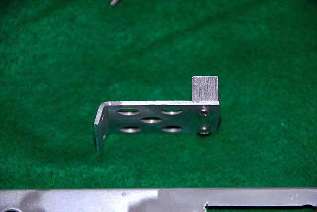
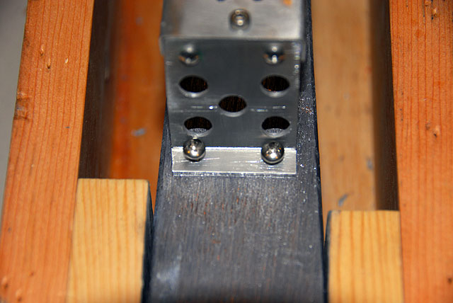
The bottom will be bent at angle to match the angle of the ballast in the hull. The top will have a piece of square stock drilled and tapped to match the top holes. You can use practically anything at the top that will give you threaded stability for the removal screw. Cut it to size inside the flanges.
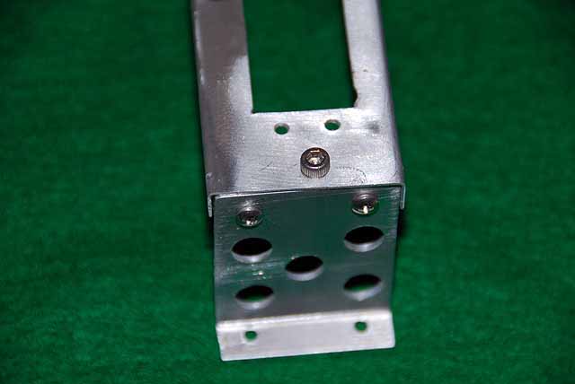
Match the top to the square stock and mark the holes and punch them. We used a 4-40 tap (drilled with a #43 bit) but you can also drill it through and bolt it. It will remain part of the mount anyway. When you have installed the upper piece slip the platform over it to mark the removal screw point for drilling. An in stock 6-32 cap machine screw was used here and it matches the rudder tiller locking screw so the ball Allen tool will fit both. The original design used an aluminum thumb screw found at the hardware store screen door repair section.
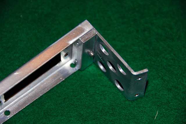
Scribe a line to bend the lower section to make the mounting tab. Note, this not a 90 degree. Clean it all up and put the thing together. Call upstairs for a Manhattan. You are home free now.
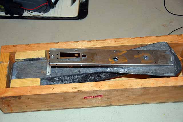
The Setup You can do this two ways, in the boat or in a ballast box. The key to positioning the platform on the ballast for balance and function is the compression post hole on the chassis and the dimple you placed in the ballast in step 2 of the EC. It is the alignment of the hole over the dimple when the ballast is angled as it would be in the boat. Got it? Good.
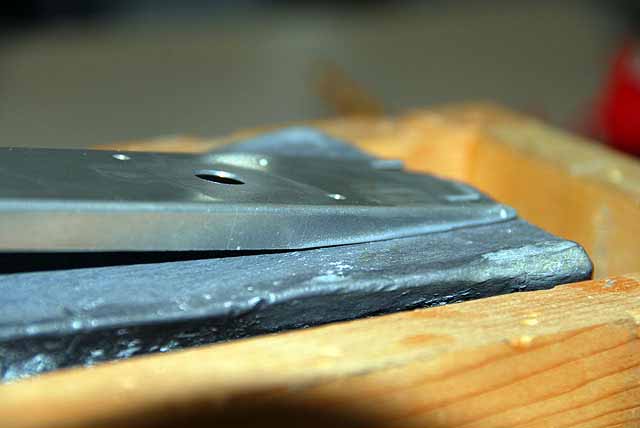
First is to feather the channel sides of the chassis so the forward edge of the chassis will be almost touching the ballast. You can see this easily in the photo. A sander, grinder or files will do it. When you have done this the chassis will not be level but slightly down at the rear. The original design was level to the planet and the DMYC wood board was flat on the ballast. A compromise was made and what is all this about. Righting moments. See Dummy Reflections.
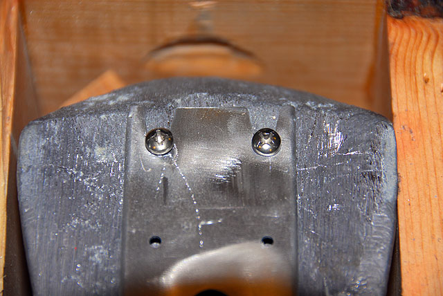
Carefully align the hole and the dimple and straight along the ballast. Using the scratch punch mark the two hole at the base of the upright and the screw points for the slide in slot at the forward end.
Carefully drill into the lead with a bit for a #6 SS sheet metal screw. You may know this but you cannot drill like normal. The bit will bind, break the bit or twist drill and break your hand. Start it and back off. Take another whack at it and back off. Keep doing this till you have the depth you need. Install the mount screws and then check the forward ones. You may need to trim the slot a bit to fit. Install the forward screws but just snug. Install the system board.
Now remove just the chassis to test and set the forward screw depth so you can slide in the chassis and it will feel firm. If all goes well there will be a solid feel to the system board with no loose movement.
Remove one of the screws holding on the square stock and Loctite (Loctite 222ms) the threads then tighten it up firmly. Do the same for the other.
You are done. Go watch a re-run of the Sopranos. The next step will be assembly of the gear to the board.
|