The Chassis
![]()
![]()
![]()
![]()
![]()
|
The Chassis
|
|
Last update, December 1, 2009
Boat System Platform
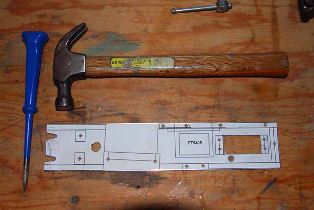
Parts: .032" - Aluminum sheet 10"x4", hobby shop or Online Metals, stock item .064" - Aluminum sheet 10"x4", hobby shop or Online Metals, stock item SS 4-40 screws and nuts - stock item Chassis Drawing - EC12 Store Tools: Scroll saw Files Dremel buffer Brake Sharp Punch Drill Threading tap
Preface What you are about to be exposed to is a design that will allow the removal of the all internal hull operations, with the exception of the rudder linkage, in a one piece unit and with one screw. Is that cool?
The advantage to this site is the R&D has been done. The numbers are correct and the system board positioning is keyed on the dimple you made in the ballast. Nonetheless, play the show and tell process so you can see the picture as you go along. The radio gear is listed where it will be installed. Have it in hand now before you start.
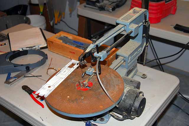
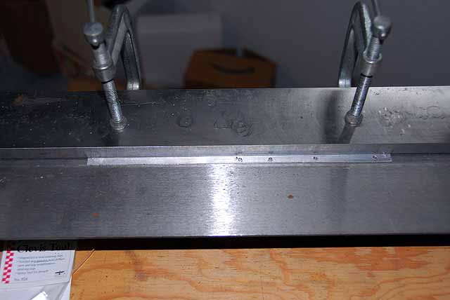
The building here will be with aluminum. Learning how to fabricate simple forms with just a few special tools will be a benefit to hobby crafting. The principle tools here are a small platform scroll saw and a bending 30" brake. This latter was found on eBay for $60 in 2003 and they are still there but less expensive. The brake requires a bench mount and is heavy enough to not warp in the center when under pressure. The steel bar that holds the piece is heavy, beveled to the cut point and sharp enough to cut your finger. This one tool add huge dimension to a shop.
You can build this chassis platform in wood and use the basic board template off the EC12 Drawing, as shown in the links on the previous page. Making the board longer for the sheetline boom mount and adding the line attach points can be worked out. Seeing the project here will easily point out the work to be done. Hobby plywood would be the choice. Online, Lonestar Balsa would be the source. Should you do this, be sure to protect the wood from moister with MinWax or the like.
Revisions: 1 Dec 09 Drawing When you enlarge the drawing increase the zoom one more level for the detail.
It is handy to have drawn out the plan for the chassis so you will have the cutouts to prepare the pieces that will be attached. The image here is not to scale if printed. When you have a drawing to scale make copies as you may need before you cut it up. Note: please check your servo choices for fit to these standard sizes and adjust to fit as needed.
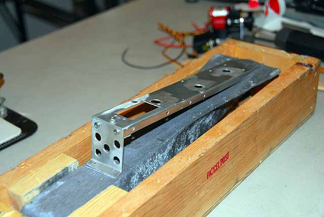
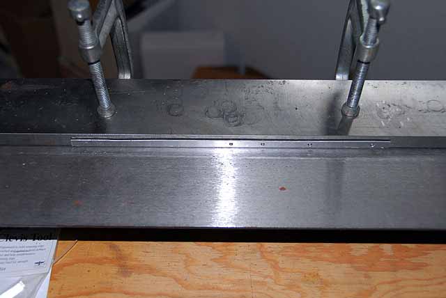
Platform Cutout The main chassis sheet is .032" and 250 x 51mm. This includes the 6mm side channel that needs to be bent down. This gives the chassis stability without center supports. Cutout the drawing for the chassis and glue stick it to the aluminum sheet. Carefully punch and drill the center of all the "X" marks for machine screws you will use and where the larger holes will be. Use the top of the vice or the holding bar on the brake so not to damage the soft aluminum. A drill bit for a 4-40 screw was used here.
Punch both ends of the channel bending line so you can later scribe a line between them for for alignment in the brake. Note: there is a hole for the aft retaining screw in the center of the chassis were it will mount to the base upright.
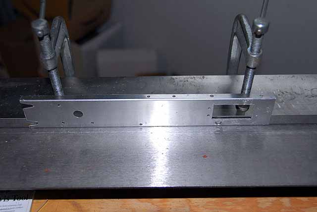
For larger holes drill small ones first. Drill a hole that you can connect a blade through for the scroll saw to cut out the rudder servo drop through. Then cut it out. The wedges at the forward end are to slide the chassis under screw heads in the ballast to secure the it. Clean up your work with a file or sanding stick and set it aside. Remember, you are building for function not a boat show.
Take a piece of scrap metal and practice bending, however you are going to do it. The channel on the chassis is only 6mm and should be crisp all the way along it. This is what gives the platform its strength using these light sheets. While you are playing with it, mark the side that you will bend. This is important so you do not bend the wrong direction for the pattern you have made. Shown here is the chassis upside down because the bend will be up towards me. One bend will have to be with the holding bar over the narrow 6mm flange. Be sure to clamp the bar well so there will be no movement while bending. Okay...Okay, find someone in town to do it for you but know what you want and can explain it.
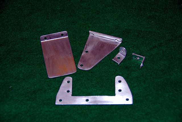
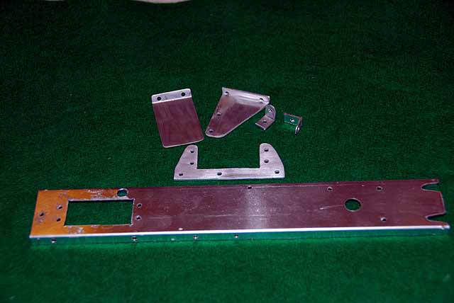
The Parts There are patterned parts on the drawing. Cut them out and glue stick them to the sheets. The outrigger and the jib servo mounts are in .064" sheet. The RX piece is .032" sheet. The brace brackets for the shaft into the bow can be anything or just bended .032". Once again, carefully punch the drilling points for the machine screws.
Go through the same process as above and set them aside.
That is enough for now. Go back to the System Board page. The building of the platform rear mount will be next. |