Tank
![]()
![]()
![]()
![]()
![]()
![]()
![]()
![]()
![]()
![]()
|
Tank
|
|
Last update, May 6, 2000 This is optional equipment…
Editing Note: This page is retained in the original text, as dated above. Please understand this tank became an instrument for multiple reasons in the development of this site and planned building by inexperience at that time. Any crude tank that can show the trim of the boat and that it is roughly within the 42-43 inch waterline of the specifications, will do just find. So will a bath tub, if anyone has one...Rick West, December 2009.
Table A table was built to support the tank so the working area was at a normal standing height. Should this be an option, consider the load bearing of the table to around 350 pounds. This table is 32" high, 48" long and 24" wide. The width was for stability. Though not shown here adjusters will be added to the legs. While not in use, this table is useful as a portable work bench.
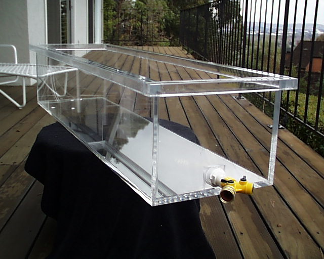
The Tank Bill Cullen followed the basic design provided in the EC12 Optimizing Manual for preparation of this tank. This book can be ordered through the Class Store. One-half inch clear acrylic was selected for the construction due to its strength and durability when exposed to water. Acrylic does not require finishing and the sharp edges bond well together to prevent water leakage. The material also provides a nicely finished and level edge around the top where the measurements would be taken. Tap Plastic Inc., provided the material and cut all parts to specifications requested. Their expertise and equipment far exceeded our garage collection of tools.
The tank is 13" wide,
48" long and 10.5" tall. The outside top edge perimeter is bordered
with 1" square acrylic to reduce side wall pressures when filled with
water. This perimeter also provides a lifting surface when moving the tank and
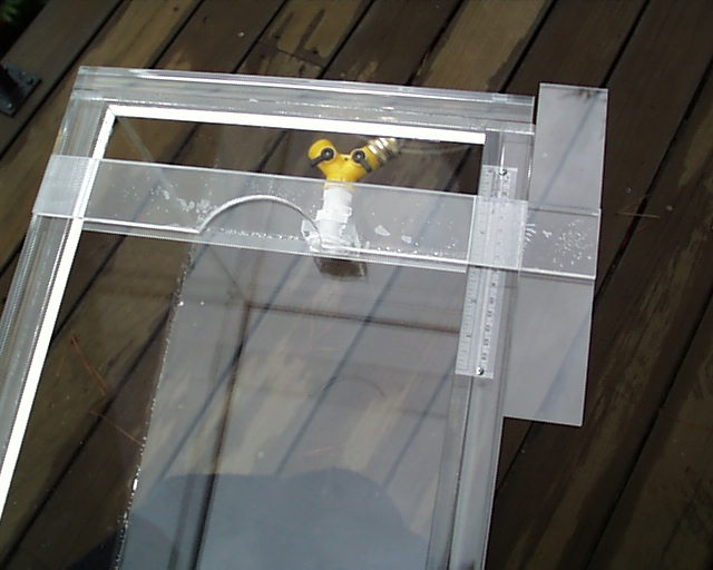
an excellent level surface for the T square. A 1/2" marine thru-hull
fitting, a dual shut-off Y valve and thread adapters were installed to
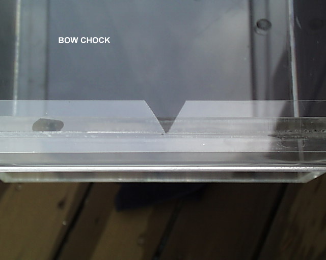
facilitate filling, adjusting water levels and emptying. The bow chock delimiter is of 1/16" acrylic, flush on the top edge and the 60 degree V is cut so the bow will touch, but not rest, on the inside edge of the tank. The bow will not drift during the LWL measurement.
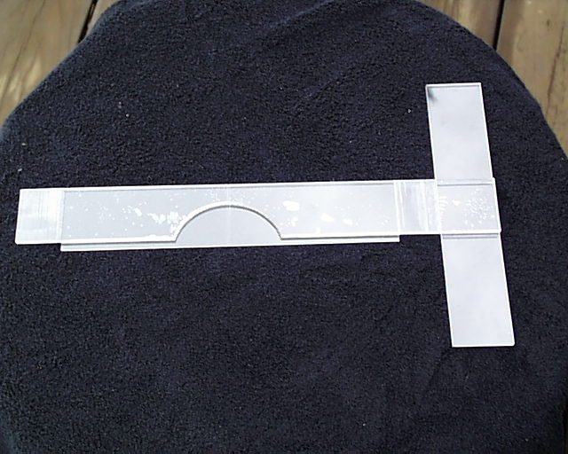
The T square is 1/4" acrylic, 2" wide with a 1/16" piece affixed to the bottom to set the measurement of the waterline. The half-moon bevel on the T square was added to prevent any possibility of the stern touching the square rather than the delimiter. This was also marked for centering the stern as the measurement is taken. A 6" ruler was mounted on the tank top and placed to represent measurements of 40 to 46 inches. The square base was routed so the it would slide over the thickness of the ruler and track without friction. The scale placement and the reading indices are departures from the drawings provided in the M2 manual. Here the scale will be read from left to right so that mistakes in the readings would be minimized. The procedures for use of the tank in the adjustment of the waterlines and trim angle will be reported on the Weigh-In page. That will proceed as the boats come to that stage which, we await eagerly.
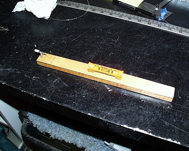
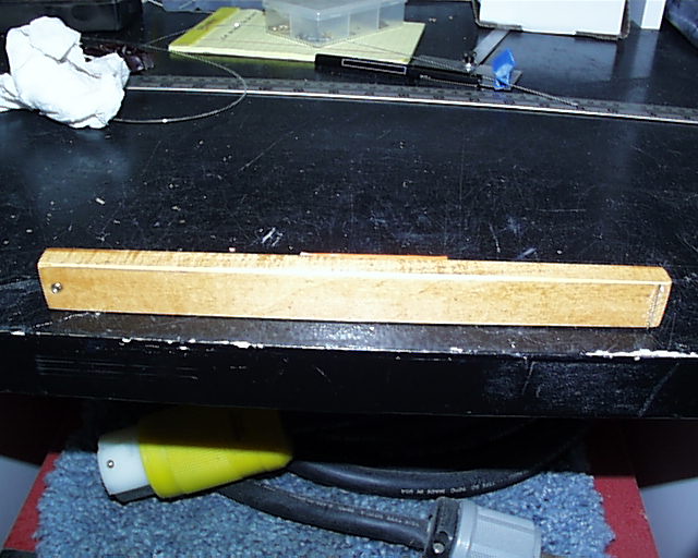
Trim Angle Tool The tool was made from 1/2" basswood to the size stated in chapter 2 of M2. This wood was chosen as it is well dried and straight grained. It was sealed and then vanished for moisture protection. A 6-32 insert and machine screw were used for the adjuster so the chart in the manual could be used for reference. A pointer was soldered to the slotted head for ease in reading the turn fractions. The bubble level was found at the hardware store. The tools weight 50 grams (1.74 ounces) when finished.
Prepare a perfectly level surface for calibration. Place a piece of glass on the surface for the tool to rest on. Remove the adjusting screw and adjust the insert till the bubble is level. During adjusting and leveling, the tool pivots on the traverse rod underneath. Put in the adjusting screw and with slight finger pressure on the stock of the tool, tighten the screw till you feel movement. You will also see the bubble move at the same time. It is very sensitive. This will zero the tool for use.
|