Round Mast Rigging
![]()
![]()
![]()
![]()
![]()
![]()
![]()
![]()
![]()
![]()
|
Round Mast Rigging
|
|
Last update, January 9, 2010
Rig the Mast
SailSetc parts (SE) and all from Midwest Model Yachting (MMY) Part photos can be seen there.
Parts: Head Fitting, MMY #119 Jumper Strut, MMY #129 or Mike Zellanack or make your own Hook mounts for Jumper, MMY #178 or make your own from good fish hooks Spreader wire housing, Sullivan Products #S522 cable and housing .015 seven strand stainless wire for the jumpers, McMaster-Carr .018 seven strand stainless wire for the shrouds or .016 solid stainless wire, Small Parts, SWX-3016-10, one coil per rig SE brass crimps, MMY #215, stock #2 leader sleeve, Berkeley Fishing, stock 1 - Spreader kit 75 mm, MMY #30 1 - Spreader kit 100 mm, MMY #31
Supplies: Sheet metal screw stock CA glue Blue tape
Tools: Drill and bits Pliers Side cutters Dremel
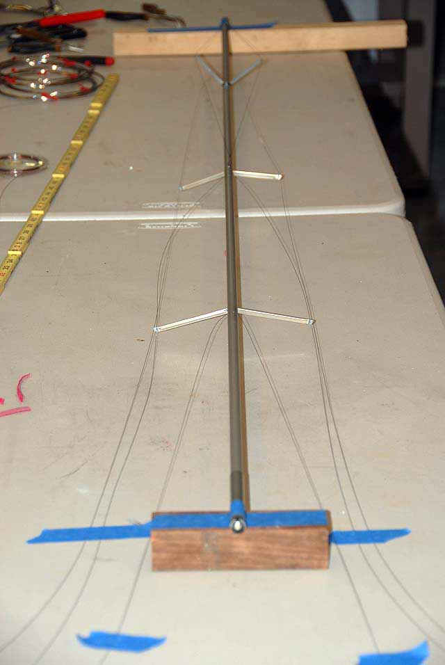
Here we will install all the mast parts except the shroud connectors. The main boom will be installed in the Rig Assembly section along with the mainsail. The jibsail will be installed on the boom and hoisted also during the assembly.
We left off with reading of internal tangs and crimping. We will get to the shrouds shortly.
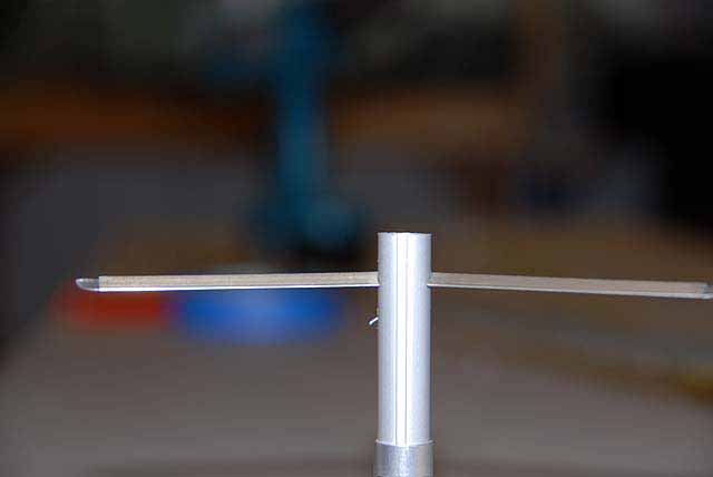
Jumpers The Zellanack aluminum jumper strut is smaller, easier to install and easy to remove the blade when packing the rigs away at the lake or storing at home. This can be seen on the Classic Rig. The SE strut is stainless steel and longer. Used as it is on the mast it does not provide an easy means to remove it for rig transport in a case. Build what you like, the process is the same.
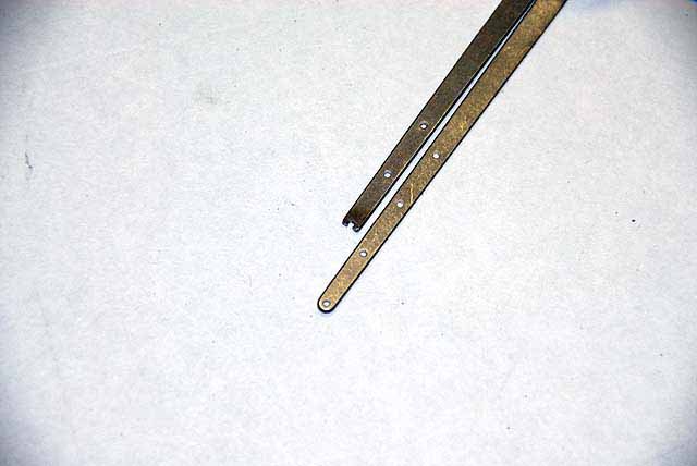
The strut shown was cut down one hole length. The hole was used as a notch for the jumper wire so it would be slipped off. Some filing is needed. The strut was mounted with two #2 sheet metal cap screws and just barely snug to the mast. This is to save the holes in the mast over time, as the strut is not a high load item. A #50 drill bit was used. The cap screws use the same tool you will see in the boom section for the adjusters, a 5/64" ball hex. Whatever screws you use will need to be considered for the ever present groove extrusion inside the mast. It is likely you will have to shorten them.
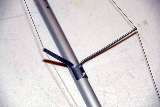
Tape the mast down on the groove. Cut a piece of wire the length of the mast that you will use. Bend a #178 hook of so it will go in the mast from the side and rotate pointing down toward the strut. Feed the wire till it is even length, slip on a crimping sleeve and lightly crimp it. Then slip on a SE sleeve that will be the sliding adjuster. Run the wires over the strut arm notch and put a piece of tape over them to hold it in place. From the lower end feed on two SE sleeves. Install a hook that you drilled for it and pass the two end pieces through the eyelet. Now run those wire ends back through the lowest sleeve. Work the ends of the wire till the wires along the jumper are taught and while holding it slide the sleeve down to hold them. There should be even tension and a nice smooth rounding at the eyelet. When satisfied, crimp it. The other sleeve is a lower adjuster when needed.
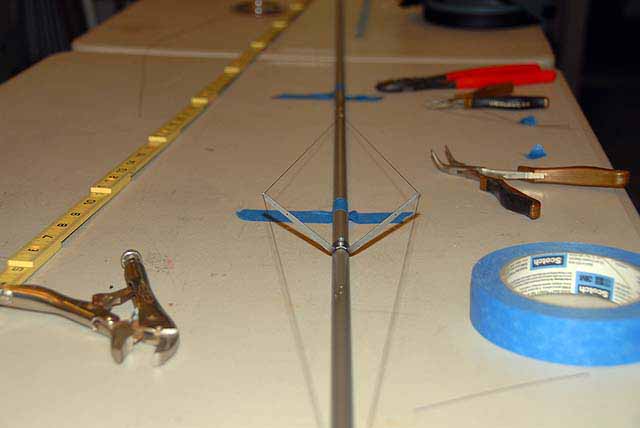
Spreaders The SE spreader kits require some work for the EC12 and the tuning method for the mast with dual spreaders. It has also been found that spreaders do not need to be out over the chainplates so these will be cut down. The tuning method for the mast is to rake the spreaders a bit aft and when there is varying tension the mast will bow forward as the tension goes up. The better news is that in standing the rig on the boat the spreaders can be inserted on the mast after the upper or mid shrouds are connected to the chainplate.
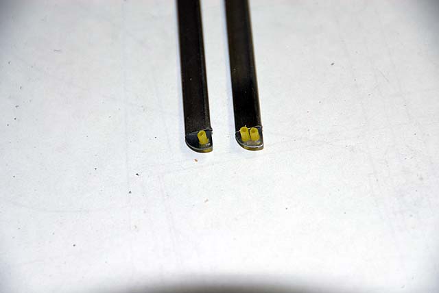
Cut the smaller spreader airfoils to 57 mm and the longer to 77 mm. Use a small diameter Dremel grinding wheel to cup one end slightly where it will fit against the mast. Clear out the chaff from the inside were the shaft will go and clean up the edges. Place the tabs that will hold the wire into the other end with the hole toward the leading edge of the airfoil. Tap them lightly till they go in. Some may be loose. Slip them in with a dab of CA glue.
The shorter one will be the upper for one wire and the longer will be the lower and have two wires.
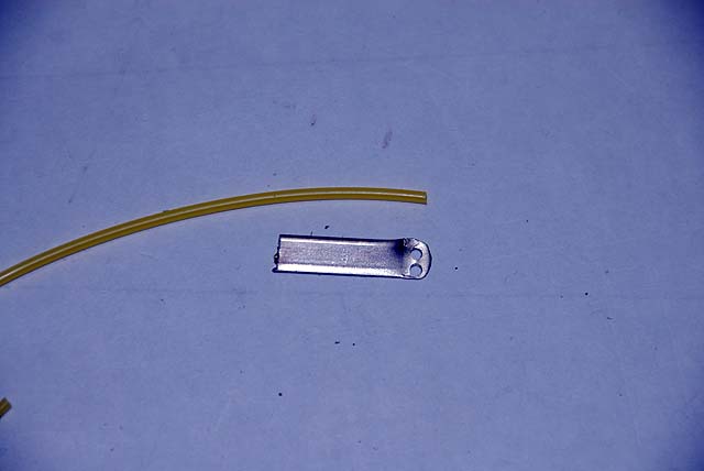
A cable housing is used on the tab ends for the wire to pass through. This housing keeps the airfoil in line when the shrouds are tensioned, prevents chafing and crimping the shrouds in transport. Drilling the tabs with a #50 bit is best using a scratch or prick punch and a drill press because the metal is hard. A hand drill wobbles too much and bits can break. Tolerances are close and there is little room for the dual wire housings. It will take some push and twist but the housing will pass through the hole and you can trim them with scissors.
An alternative, if you do not have a drill press is to add 5 mm to the length of the airfoils, crush to tip and then punch and drill. A piece of scrap airfoil shown here give you the look.
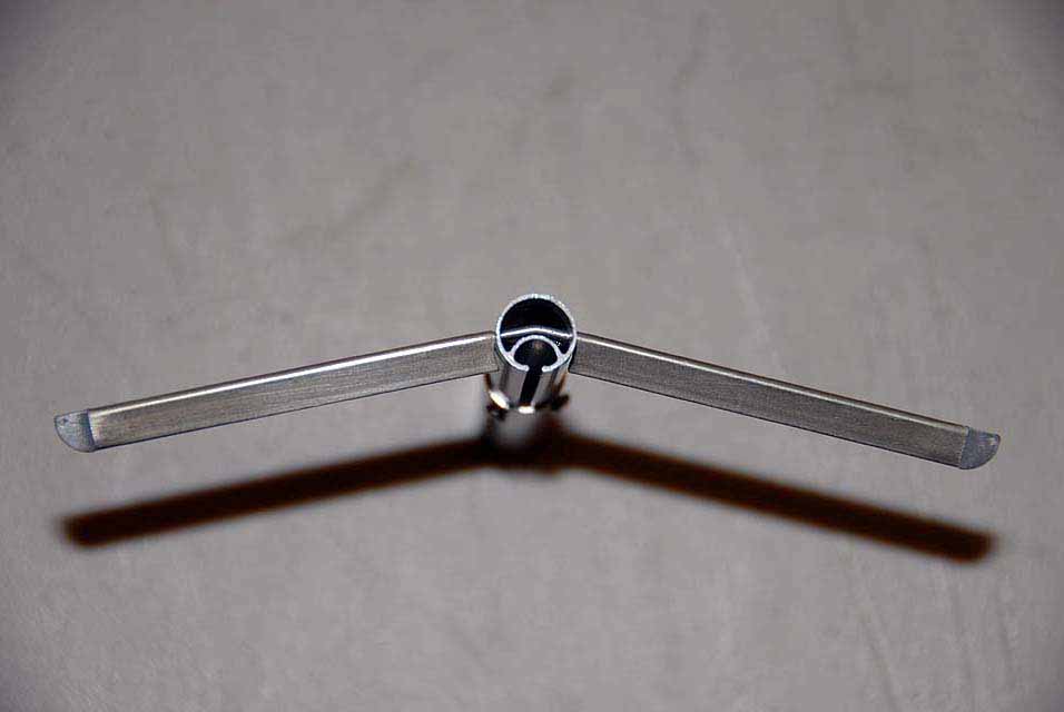
The shafts are 50 mm so make a mark at 25 for the center. Marking with the jaws of small pliers bend the shaft slightly. Work the shaft till it will insert into the airfoil. On a test piece of mast drill a #53 bit hole and then insert the shaft, rotate it till it points aft. If this does not work for you enlarge the hole slightly till the shaft will rotate to the desired position. Work the shaft onto the spreader till it is snug against the mast and the center of the bend is centered in the mast. Align the shaft straight with the airfoil then put a dab of CA glue in the opening under the shaft and force it into the airfoil with a needle or T pin. Let it cure.
Work the other airfoil on the shaft for fit on the test piece and check your work.
Shroud Installation If you have not prepared and drilled the shroud wire holes, please do so now. Make sure you are 10-12 mm below the spreader holes so not to interfere with the spreader shafts.
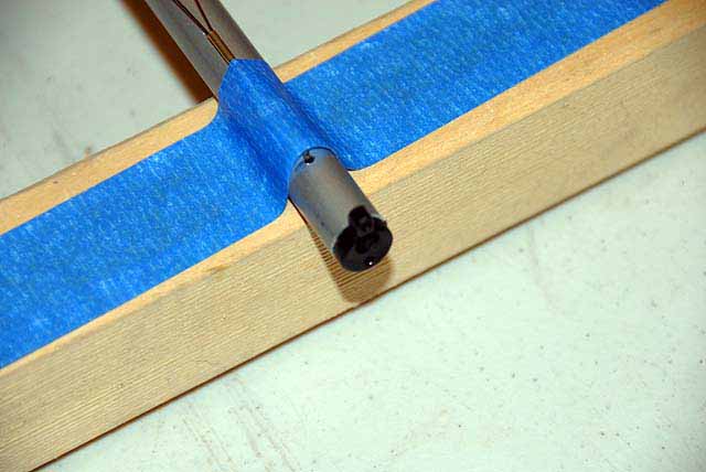
Tape the mast groove flat to a table and starting at the lower shroud holes, feed the wire up the mast and out the head. Install the tang, draw it back down the mast and cut the wire about a foot below the heel of the mast. It will take about 28 feet of wire.
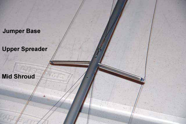
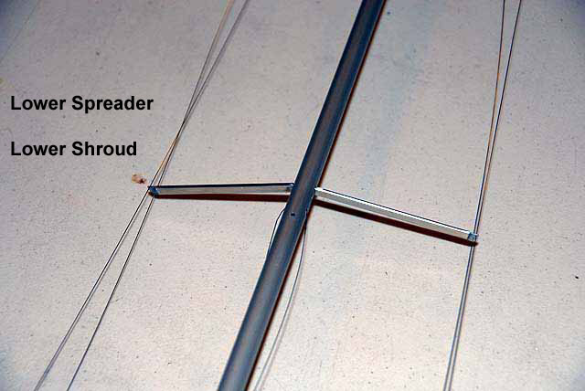
Feed the upper shrouds through the shorter spreader. Consider where you like to work when you are setting up the boat. Here, the boom control adjusters and the spreader shafts are on the starboard side. Install the upper spreader. Feed the upper shrouds through the forward hole of the lower spreader. This way you will see immediately which shroud in which when standing the rig. Place the mid shrouds through the aft one and install the lower spreader.
Organize the shrouds on the table making sure there are no twists or one slipping under the jumper wires. Looks good, huh?
If your drilling for the jumpers were dead center on the leading edge of the mast and the spreader holes at 90 degrees to them, then all will line up nicely. Do not be concerned if the spreaders do not look that way. When they are tightened they will align if the holes are right. The same goes for the angle of the spreader shafts. The angle can be adjusted and to each other if needed when the rig it up on the boat.
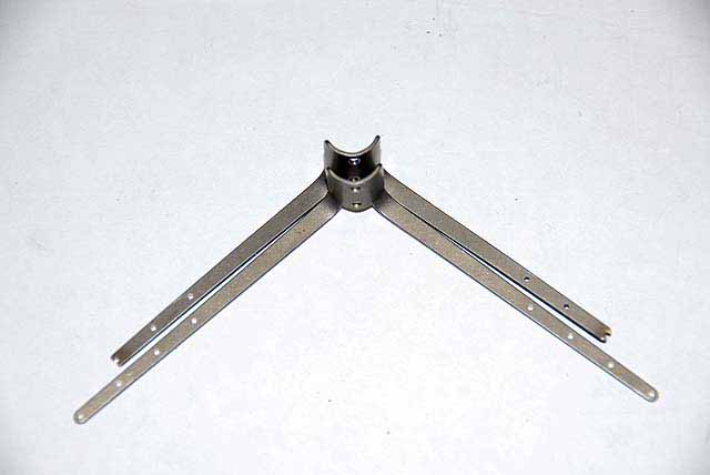
Mast Head Fitting Install the the fitting, as it is and it will firmly fit. Tape up a crane so not to mare it. Place it in a small vice to the hilt of the bend. Tap it with a mallet till crane is at 90 degrees to the mast. This is needed for this specific rig so you will be within the 72" specification in the Rules. The hole in the fitting under the crane is for a hook to the head of the mainsail. Later you can drill along side the crane for the wire of a mast fly if you like.
Crimp a 62" wire onto the crane for the backstay with a loop at the lower end for the adjusting line.
"Hey Vern, lets take a break and watch a Sopranos and count how many times Tony uses the F-word?"
|