SE Rig Assembly
![]()
![]()
![]()
![]()
![]()
![]()
![]()
![]()
![]()
![]()
|
SE Rig Assembly
|
|
Last update, March 10, 2010
Assembly of the Vector Rig
SailSetc parts (SE) and all from Midwest Model Yachting (MMY) Part photos can be seen there.
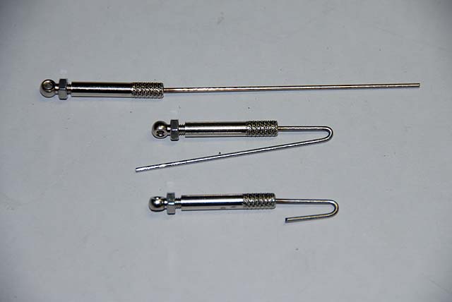
Parts: Most parts used here are on the main boom page Main boom assembly Jib boom assembly Mast Butt and Pin, #MMY 142B or make your own Mast crane, MMY #116A 6 Rigging screws, MMY #131 2 spare eyelet screws 20 mm, MMY #44
Supplies: Blue tape Screws Crimp sleeves Rigging wire Bowsies Hooks 3 mm SS Nylock nuts
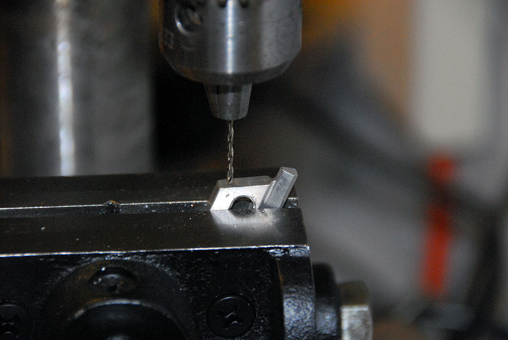
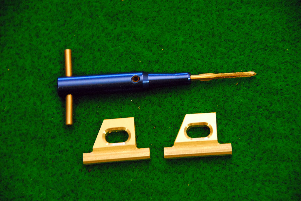
Tools: Drill and bits Drill Press, handy Drill Press Vise 2-56 tap, LXTH9, Tower Hobbies Screwdrivers Pliers Crimper or small Vise Grips Wire cutters
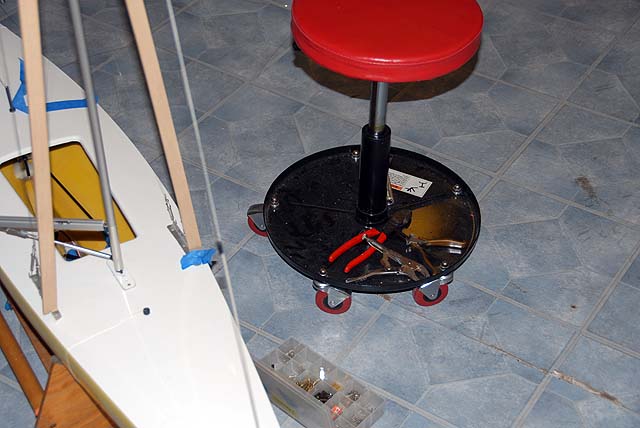
Settle in, you are going to be here for a while.
Putting the Vector Rig together is similar to what has been done for years. The rig can be raised on the deck without sails because the mounting and controls for the sails were prepared to accommodate this convenience. Installing and tuning the rig without the sails gives you time to prepare the environment properly and with better visibility and change them at the lake. Lastly, it is less handling of the sails.
The jib was designed as a unit with the boom and all controls installed but the sheetline. This allows the unit to be removed from the rig by two hooks and the sheetline connection. Likewise, the jibsail can be removed like the main from the boom and with the forestay still in the luff. The forestay can then be removed and installed on another sail with the small connecting loops still formed.
The minor complication is the pin for the mount on the bow fitting of the boom. A pin was used here to lessen abrasion on the downhaul line and allow the connecting loop to pass off the boom rather than replacement. This pin can be pushed back to release the forestay and the reverse when installing the connector. A dab CA glue outside one side of the pin should keep it from moving around when there is no pressure and rattling around in your vehicle.
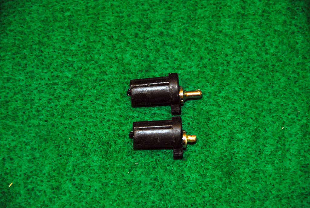
Gooseneck and Vang Mounts Vang and mounts for the vang and gooseneck were custom made. It has no bearing on this building phase. Any of the EC12 suppliers of rigging parts have their versions of these parts.
You will note the lower section of the mast is sleeved. This section is 200mm long and contains the gooseneck and vang mount with the butt plug and mast step pin. This process is standard here at Delta to enhance storage convenience, installing a rig in a 62" crate and for hot swapping should a rig be damaged when on the road. It has no bearing on the assembly process here.
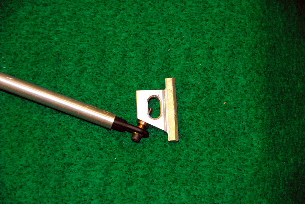
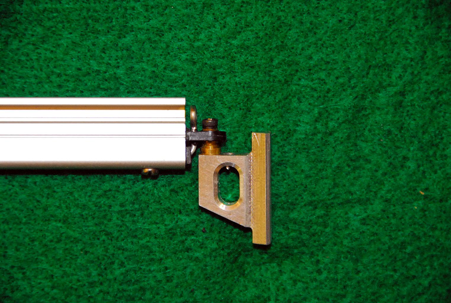
Mast Mounts: The slide groove mounts for the gooseneck and the vang were drilled with a #50 bit and tapped for 2-56 threads. Install these mounts on the mast and mount the boom and vang. A drill vise is handy here.
Using a 160mm compression vang, the mounts were set at 70mm apart on the mast and taped for a locking screw to not slide. This was determined using a right angle square against the mast and main boom. (Note: A mount must not move. Doing so will change the angle of the boom and hence, the tension on the leech.) The mount to the underside of the boom was marked for drilling using a square and mid range threads on the vang. This was drilled and mounted with #2 5/16" tapping screws.
SE Gooseneck/Kicking Strap Option This major part assembly is called Gooseneck/kicking strap at SE. That is for little boats and so it will be the vang on the EC12.
Because the gooseneck body is not adjustable when installed there is a question as to where it should be in relation to the sail. The tack is first issue then the clew. So, let's wait on this a bit.
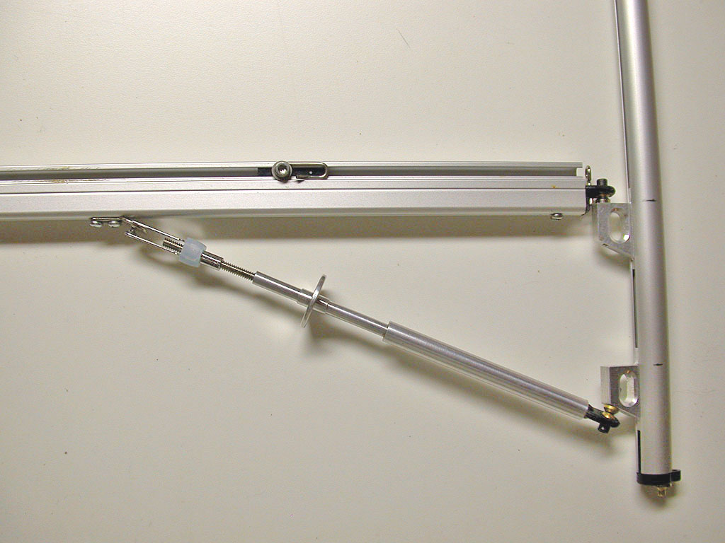
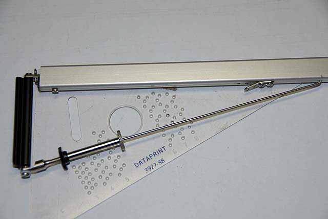
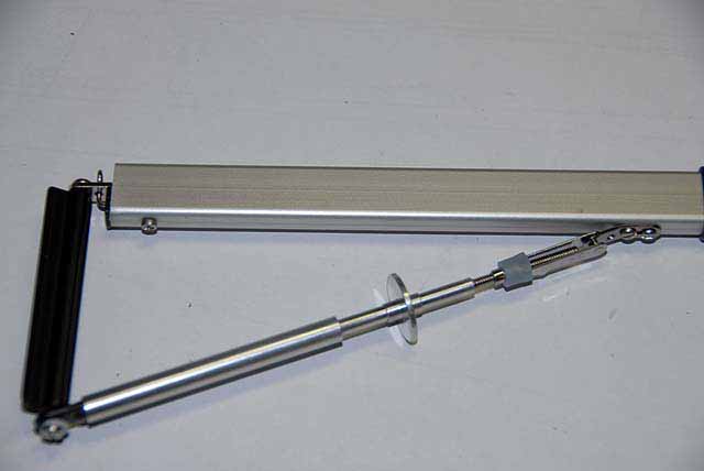
First install the boom to the mounting body and then the vang to the base. Over lay this on a right triangle so that you can adjust the vang to produce a right angle at the gooseneck to the mast at the mount. Play with this till you understand where things are loose and then make a mark on the boom where the far point of the vang hook is. This mark should be considered with upward pressure on the boom and not while it is drooping. Drill a #51 bit hole, insert the hook and reconnect it to the vang. Okay, now that I told you how to do it the number for the hole is 183 mm from the gooseneck end and this includes the black insert.
In one of the photos here a solid spring vang installed. This is an in stock vang that will be tested on another rig. The photo is shown for those of you that prefer a more rigid vang with a hard mount to the boom. The mount shown is Pekabe tang that was in stock. One could be made from sheet aluminum. A 4-40 quick link from Sullivan was use for the connection. The photo with the SE vang and the hook mount to the boom is on the same boom so either one can be used during testing.
The SE vang was used in five 2007 events including the NCR and worked fine. The SE vang (kicking strap) will do the job just. However, the crafted solid vang is a preference by some in the field for their tuning processes and for sheet vanging techniques. Parts Note: The mount is called Gooseneck Body at SE. It can be ordered separately of the assembly from SE. You would then need the gooseneck tang, #103t, in the SE catalog. These parts are not stocked at MMY but you could inquire. To mention again here, the SE catalog is free by email request.
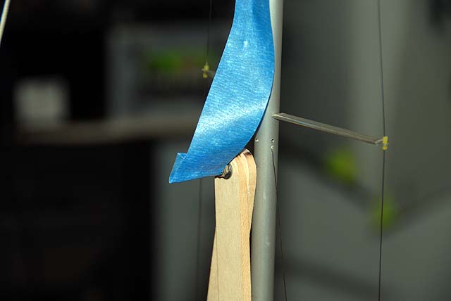
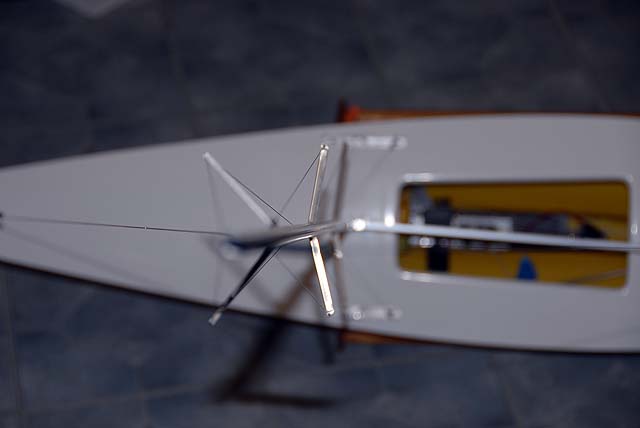
Cut a 98 mm length of 1/2" mast sleeve and clean it up. Slide it on the mast for fit. This sleeve has several uses. First it is a screw support for mounting the gooseneck body. Secondly, it supports the lower mast so lower-lower shrouds are not needed.
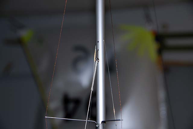
Mast Butt Fitting The mast step used in the decking section was 1/8" acrylic with an aluminum plate to protect the deck from punctures. If you are using the SE mast heel fitting you will notice a bevel to the pin and that the pin is too long. Here the bevel was filed out with a flat needle file and the pin was shortened so it would rest on the plate. Install it on the mast. You may secure it but it seems to hold its place nicely. ------------------------- Update to continue Prep Make sure the removable compression strut is standing from the ballast. A jib forestay cripple of string, hooks and bowsie was prepared to assist in holding the mast in position for setting the shrouds. A hook at the top in the emergency hole is handy. A 66" piece of rigging wire was cut and secured to the crane with a crimp. A loop was made in the lower end for the string and bowsie that will adjust the backstay tension. This line will terminate at the hook to the deck plate.
The deck was leveled in the cradle to match the floor and the planet. A sheetrock T-Square is used here for the initial vertical setting. A tall shop mast boat beam divider is clipped to the chainplate forward hole loosely to reach at least the mid spreader where alignment is checked. If you have someone to hold the mast while you adjust and tie off the forestay cripple and the backstay, things move along more easily.
Here the pin in the heel fitting is the same size as the mast step so at this point the mast will stand alone if properly aligned fore and aft. Nonetheless, a helper on the mast would be handy, as you move forward.
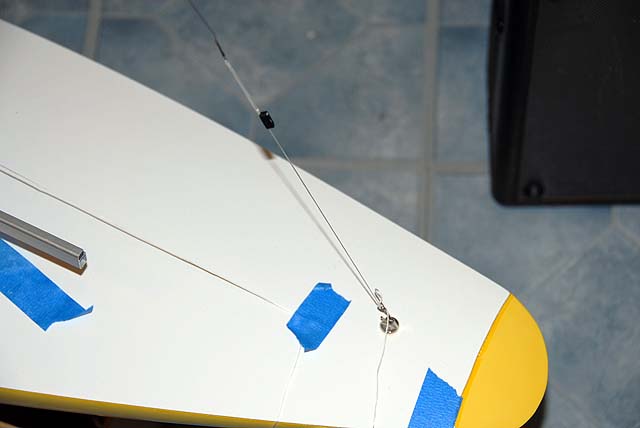
Shrouds A 1/2" piece of wood stock was used to uniformly measure the bending of the wire that will hook to the chainplate. Nylock nuts are treaded on the eyelet screws. If you are going to be using the SE rigging parts, you might want to invest in a nut driver with a 5.5 mm socket for your toolbox. Gather your tools and get with it.
The mid shroud is done first because that is where the divider is. Run the body of the rigging screw up about a quarter of the way, snug down the wire, checking the divider (it can lean a bit toward you) and crimp it. Move to the other side and do the other mid shroud. Now fuss with this till the mast is centered on the divider with about 2.5 pounds of tension. The jumper shrouds should be unrestricted. Stand in front of the boat to get a perspective that it looks centered.
You can release your helper now. Install the upper shroud in the same manner, just snug. The lower shroud should be loose but not drooping. This shroud is a bend limiter and so you want some flexibility to allow it to go forward a bit when you want the foot of the main to flatten and at another time to allow shape into the panel when drive is needed.
Place about 1.5 pounds of tension on the backstay and increase the shroud tension to 3.5 pounds for the A heavy rig shown here. (2.5 pounds would be good for the light rig.) Lay the boat over in the cradle and begin adjusting for straight mast athwartships. There will be some fore and aft bend because of tension on the spreaders and the slight pulling of the backstay. Clockwise turns on the locking nut pulls the mast toward the shroud and counter-clockwise away when the body of the screw is snug. When all is set, it should be in the same place when you rig at the lake.
When you are happy with the location of the rigging screws on the chainplate, trim the bend length and close them just enough they will not come off during transport of the boat.
This section is complete Work suspended till mid March for the following
Install the Mainsail
Install the Jibsail
Complete the Post
Pre-Tune |